
Install Instructions


18 103448-08- 9/16
IV. Venting A. General Guidelines (continued)
A. General Guidelines
1. Listed Vent/Combustion Air Systems
a. Install vent system in accordance with “Venting
of Equipment” of the National Fuel Gas Code,
ANSI Z223.1/NFPA 54 or “Venting Systems
and Air Supply for Appliances” of the Natural
Gas and Propane Installation Code, CAN/
CSA B149.1, or applicable provisions of local
building codes. Contact local building or re
ofcials about restrictions and installation
inspection in your area.
b. The Alpine is a Direct Vent (sealed combustion)
boiler. Install vent system in accordance to these
instructions. Combustion air must be supplied
directly to the burner enclosure from outdoors
and ue gases must be vented directly outdoors.
c. The following combustion air/vent system
options are listed for use with the Alpine boilers
(refer to Table 4):
i. Two-Pipe CPVC/PVC Vent/Combustion
Air System - Separate CPVC/PVC pipe
serves to expel products of combustion and
separate PVC pipe delivers fresh outdoor
combustion air. Refer to Part B for specic
details.
ii. Two-Pipe Polypropylene Vent/Combustion
Air System - Separate rigid or exible
polypropylene pipe serves to expel
products of combustion and separate rigid
polypropylene or PVC pipe delivers fresh
outdoor combustion air. Refer to Part C for
specic details.
iii. Two-Pipe Stainless Steel Vent/Combustion
Air System - Separate stainless steel pipe
serves to expel products of combustion
and separate PVC or galvanized steel pipe
delivers fresh outdoor combustion air. Refer
to Part D for specic details.
d. Vent connectors serving appliances vented by
natural draft shall not be connected into any
portion of mechanical draft systems under
positive pressure.
2. Vent/Combustion Air Piping
a. Do not exceed maximum vent/combustion air
lengths listed in Table 5A. Vent/combustion
air length restrictions are based on equivalent
length of vent/combustion air pipe (total length
of straight pipe plus equivalent length of
ttings). Table 6A lists equivalent lengths for
ttings. Do not include vent/combustion air
terminals in equivalent feet calculations. Use
vent/combustion air equivalent length worksheet
provided in Table 6B.
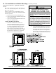
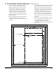
b. Maintain minimum clearance to combustible
materials. See Figure 2A or 2B for details.
c. Enclose vent passing through occupied or
unoccupied spaces above boiler with material
having a re resistance rating at least equal to the
rating of adjoining oor or ceiling.
Note: For one or two family dwellings, re
resistance rating requirement may not need
to be met, but is recommended.
d. Slope horizontal vent pipe minimum 1/4 in/ft
(21 mm/m) downward towards the boiler.
Les chaudières de catégories I, II et IV doivent
présenter des tronçons horizontaux dont la pente
montante est d’au moins 1/4 po par pied (21
mm/m) entre la chaudière et l’évent.
e. If possible, slope horizontal combustion air
pipe minimum 1/4 in/ft (21 mm/m) downward
towards terminal. If not, slope towards boiler.
f. Use noncombustible ¾ in. pipe strap to support
horizontal runs and maintain vent location and
slope while preventing sags in pipe. Do not
restrict thermal expansion or movement of vent
system. Maximum support spacing is 4 ft. (1.2
m). Avoid low spots where condensate may
pool. Do not penetrate any part of the vent
system with fasteners.
Les instructions d´installation du système
d´évacuation doivent préciser que les sections
horizontales doivent être supportées pour
prévenir le échissement. Les méthodes et les
intervalles de support doivent être spéciés.
Les instructions divent aussi indiquer les
renseignements suivants:les chaudières de
catégories II et IV doivent être installées de
façon à empêcher l´accumulation de condensat:
et si nécessaire, les chaudières de catégories
II et IV doivent être pourvues de dispositifs
d´évacuation du condensat.
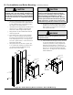
g. For multiple boiler installations with vertical
roof terminals, separate vent pipes from multiple
boilers may be piped through a common conduit
or chase so that one roof penetration may be
made.
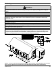
3. Vent/Combustion Air Terminals
Install venting system components on exterior
of building only as specically required by these
instructions (refer to Figure 4).
a. Use only listed vent/combustion air terminals.
i. Horizontal Sidewall Venting: For models
ALP080B thru ALP285B, use coupling for
vent terminal and 90° elbow for combustion
air intake terminal as shown in Figure 5).
Alternate staggered and snorkel terminations
are shown in Figure 6A and Figure 6B.