
Install Instructions

103448-08 - 9/16 31
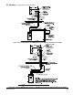
3. Near-Boiler Vent/Combustion Air Piping
Refer to Figure 10A and the following Steps:
a. Models ALP150BF thru ALP210BF (oor
mounted) and ALP285B only:
Apply supplied dielectric grease (grease pouch
attached to two-pipe vent connector) to gasket
inside vent section of 3 in. x 3 in. or 4 in. x 4 in.
two-pipe vent connector. The grease will prevent
gasket rupture when inserting vent pipe and
gasket deterioration due to condensate exposure.
b. Install provided Schedule 40 x 30 in. (760 mm)
long CPVC pipe into the vent section of the
connector with a slight twisting motion and
secure by tightening the worm band clamp screw.
c. All CPVC vent components supplied with boiler
inside vent carton [Schedule 40 x 30 in. (760
mm) long CPVC pipe and Schedule 80 CPVC
90° Elbow] must be used for near-boiler piping
before transitioning to Schedule 40 PVC (ASTM
2665) pipe components for remainder of vent
system. The 30 in. (760 mm) long CPVC straight
pipe may be cut to accommodate desired vent
conguration provided both pieces are used
in conjunction with CPVC 90° Elbow before
any PVC components are used. Ensure that the
CPVC 90° Elbow is the rst elbow used in the
vent system as it exits the boiler.
d. Insert Schedule 40 PVC combustion air pipe
(installer provided) into the combustion air
section of the connector with a slight twisting
motion and secure by tightening the worm band
clamp screw.
e. Clean all vent and combustion air pipe joints
with primer and secure with transition cement.
Follow application instructions provided on
primer and cement bottles.
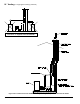
4. Field Installation of CPVC Vent Pipe - Wall
Mounted Boiler Builds
a. The wall mounted boiler builds do not require
using 3 in. Schedule 80 CPVC 90° elbow for
near-boiler vent piping. Refer to Figure 10B and
the following Steps:
b. Apply supplied dielectric grease (grease pouch
attached to 90° vent elbow outlet inside air
box) to gasket inside vent elbow. The grease
will prevent gasket rupture when inserting vent
pipe and gasket deterioration due to condensate
exposure.
c. Insert provided 3 in. Schedule 40 x 30 in. long
CPVC pipe through air box top combination
vent/combustion air collar vent opening and slide
down with a slight twisting motion, until the pipe
lower end is rmly inserted into female end of
factory installed 90° elbow vent connector.
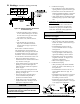
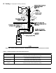
1. Components
a. See Table 7A for CPVC/PVC vent and
combustion air components included with boiler.
b. See Table 7B for CPVC/PVC installer provided
vent and combustion air components required for
optional horizontal snorkel terminals shown in
Figure 6B.
c. See Table 7C for CPVC/PVC installer provided
vent and combustion air components required for
optional vertical roof terminals shown in Figures
7A and 8.
d. See Table 7D for installer provided components
required for optional IPEX low prole horizontal
termination shown in Figures 6D and 6E.
e. See Table 7E for installer provided components
required for optional DiversiTech (HVENT) low
prole horizontal termination shown in Figures
6D and 6F.
f. See Table 7F for installer provided components
required for optional IPEX FGV concentric
horizontal or vertical terminations shown in
Figures 6G, 7B and 7C.
g. See Table 7G for installer provided components
required for optional DiversiTech (CVENT)
concentric horizontal or vertical terminations
shown in Figures 6G, 7B and 7C.
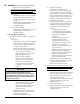
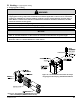
2. Field Installation of CPVC/PVC Two-Pipe
Vent System Connector
Refer to Figure 9 and following steps:
a. Position the CPVC/PVC vent connector and
gasket onto boiler rear panel and insert vent
connector inner stainless steel vent pipe into heat
exchanger vent outlet.
b. Align vent connector plate and gasket clearance
holes with rear panel engagement holes. Then,
secure the connector and gasket to the panel with
six mounting screws.
c. Attach ue temperature sensor wiring harness
(taped to boiler rear panel) female connectors to
the sensor male spade terminals. Failure to do
so will prevent boiler from starting and boiler
display will ash Red and display Limit String
Fault (see Section XII “Troubleshooting” for
details).
NOTICE
Flue temperature sensor harness must be
connected to ue temperature sensor for the
boiler to start-up and operate properly. The
installation is not complete unless the harness
and the sensor are interconnected.
IV. Venting B. CPVC/PVC Venting (continued)