
Install Instructions


46 103448-08- 9/16
1. Components
a. For use on models ALP080B through ALP285B,
U.S. Boiler Company offers sizes 3 in. and 4 in.
vent pipe and ttings shown in Table 10A. It
is the responsibility of the installing contractor
to procure stainless steel vent system pipe and
related components.
b. Alternate listed stainless steel vent system
manufacturers and components are shown in
Table 10B.
c. Where the use of “silicone” is called for in the
following instructions, use GE RTV 106 or
equivalent for the vent collar. Seal galvanized
combustion air piping sections with any general-
purpose silicone sealant such as GE RTV102.
Seal PVC combustion air piping sections with
PVC cement.
d. Do not drill holes in vent pipe.
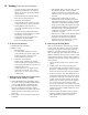
2. Field Installation of CPVC/PVC Two-Pipe
Vent System Connector and PVC to Stainless
Steel Adapter - Floor Mounted Boiler (F)
Builds
a. Models ALP080B(F) through ALP285B(F):
Install CPVC/PVC Two-Pipe vent system
connector. Follow instructions in “2. Field
Installation of CPVC/PVC Two-Pipe Vent
System Connector” under “B. CPVC/PVC
Venting.” See also Figures 9 and 17.
b. Apply provided dielectric grease (grease pouch
taped to the vent system connector) all around
to the vent or air connection inner red silicon
gasket.
c. Push and twist PVC to stainless steel adapter
into two-pipe vent system connector vent or
combustion air supply port until bottomed out.
See Figure 17.
d. Tighten the worm band clamp screw to secure
PVC to stainless steel adapter.
e. Do not install PVC to stainless steel adapter
at the lower combustion air supply port of the
two-pipe vent system connector when using PVC
pipe for combustion air supply to boiler.
3. Field Installation of PVC to Stainless
Steel Adapter into 90° Vent Elbow – Wall
Mounted Boiler (W) Builds
a. Models ALP080B (W) through
ALP210B(W): Carefully insert extended PVC
to stainless steel adapter (105290-01) from top
through air collar plate assembly and plate gasket
vent opening into boiler air box.
b. Apply provided dielectric grease (grease pouch
taped to the vent elbow) all around to the vent
elbow inner red silicon gasket.
c. Align the adapter end with the elbow inlet and
slide it down with a slight twisting motion until
the adapter lower end is rmly inserted into the
elbow.
d. Tighten the elbow worm band clamp screw to
secure PVC to stainless steel adapter.
e. Install PVC or galvanized steel pipe onto the air
plate assembly combustion air inlet collar and
seal around vent and air pipe with Sil-Bond RTV
4500 or equivalent caulk. See Figure 15A.
WARNING
Failure to properly secure the vent adapter lower
end into the elbow with the clamp could lead to
property damage, personal injury or loss of life.
IV. Venting D. Stainless Steel Venting (continued)