
Install Instructions

52 103448-08- 9/16
V. Condensate Disposal
A. Condensate Trap and Drain Line
1. All condensate which forms in the boiler or vent
system collects in the sump under heat exchanger
and leaves the boiler through factory installed
condensate trap.
2. The trap allows condensate to drain from sump
while retaining ue gases in the boiler. The trap
has factory installed overow switch, which shuts
down the boiler in the event the drain line becomes
obstructed, preventing proper condensate removal.
Refer to Section XI “Service and Maintenance” for
condensate trap and condensate overow switch
removal and replacement procedure, if required.
3. Note the following when disposing of the
condensate:
a. Condensate is slightly acidic, typical pH around
3.5 - 4.5. Do not use metallic pipe or ttings in
the condensate drain line. Do not route the drain
line through areas that could be damaged by
leaking condensate.
b. Do not route or terminate the condensate drain
line in areas subject to freezing temperatures.
c. If the point of condensate disposal is above the
trap, a condensate pump is required to move
the condensate to the drain. Select a condensate
pump approved for use with condensing
furnaces. If overow from the pump would
result in property damage, select a pump with an
overow switch. Wire this switch in series with
installer provided external high limit, to shut off
the boiler, and, if desired, in series with installer-
supplied alarm, to trigger an alarm in the event
of overow.
d. Do not attempt to substitute another trap for one
provided with the boiler.
e. In order for boiler to work properly, the boiler
must be leveled during installation.
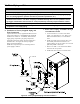
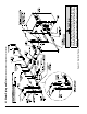
4. The condensate trap connection is located at
boiler left side, below inlet and outlet water pipe
connections. Refer to Figures 1A, 1B, 1C and 19.
5. Condensate trap must be lled up with water,
prior to boiler start-up and before connecting any
condensate line to the boiler to insure combustion
products cannot escape from operating boiler. To ll
the trap, inject water in the amount of 1 cup (240ml)
through condensate trap connection. Do not overll
the trap.
6. Install tee for condensate overow and vent as
shown in Figure 19.
WARNING
Asphyxiation Hazard. Failure to ll the
condensate trap with water prior to boiler start-
up could cause ue gas to enter the building,
resulting in personal injury or death.
7. If any additional condensate drain line is needed,
construct the extension from PVC or CPVC
Schedule 40 pipe. The factory supplied ¾ in. x 5-5/8
in. long PVC coupling, located in the miscellaneous
parts carton, must be used to connect drain line to
the condensate trap. Do not over tighten coupling
compression nuts when connecting drain line and
condensate trap.
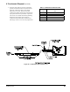
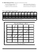
8. Size condensate drain line, pump and neutralizer
(if using other than manufacturer neutralizer kit) to
accommodate maximum condensate ow shown in
Table 11 “Maximum Condensate Flow”.
WARNING
Asphyxiation Hazard. Failure to install the
condensate drain in accordance with the above
instructions could cause ue gas to enter the
building, resulting in personal injury or death.
NOTICE
Boiler condensate is corrosive. Route
condensate drain line in a manner such
that any condensate leakage will not cause
property damage.
Some jurisdictions may require that
condensate be neutralized prior to disposal.
Use materials approved by the authority
having jurisdiction.
B. Condensate Neutralizer Installation
1. Some jurisdictions may require that the condensate
be neutralized before being disposed of. Follow
local codes pertaining to condensate disposal.
2. A condensate neutralizer kit (P/N 101867-01) is
available as optional equipment. Follow local codes
and instructions enclosed with the kit for condensate
neutralizer installation.