
Install Instructions

54 103448-08- 9/16
A. Installation of Factory Supplied Piping and
Trim Components
Alpine boilers have factory supplied Miscellaneous Part
Carton (P/N 102942-01 – ALP080B through ALP210B;
102942-02 or 103676-01 – ALP285B), which includes
supply piping components, gas piping components,
Temperature & Pressure Gauge, Pressure Relief Valve
and Drain Valve. See Figure 20 “Factory Supplied
Piping and Trim Installation”.
Install these components prior to connecting boiler to
system piping as follows:
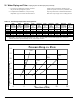
VI. Water Piping and Trim
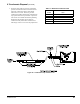
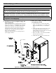
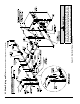
Figure 20: Factory Supplied Piping and Trim Installation
1. Relief Valve Piping, ALP080B through
ALP210B Boiler Models
a. Locate and remove ¾ in. NPT x close black
nipple, ¾ in. NPT black tee, ¾ in. MPT x ¾ in.
FPT Pressure Relief Valve, ¾ in. NPT Drain
Valve.
b. Install close nipple into tee branch, then, screw
the assembly into boiler left side front ¾ in.
tapping making sure tee run outlets are in vertical
plane and parallel to boiler side.
c. Mount ¾ in. MPT x ¾ in. FPT Pressure Relief
Valve into the tee top outlet.
d. Install Drain Valve into the tee bottom outlet.
NOTICE
Failure to properly pipe boiler may result in improper operation and damage to boiler or structure.
Install boiler so that the gas ignition system components are protected from water (dripping, spraying,
rain, etc.) during appliance operation and service (circulator replacement, etc.).
Oxygen contamination of boiler water will cause corrosion of iron and steel boiler components, and
can lead to boiler failure. U.S. Boiler Company’ s Standard Warranty does not cover problems caused
by oxygen contamination of boiler water or scale (lime) build-up caused by frequent addition of water.
Do not ll boiler with softened water to prevent chloride contamination.
Installation is not complete unless a safety relief valve is installed into the tapping located on left side
of appliance or the supply piping.