
Install Instructions

103448-08 - 9/16 55
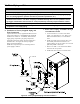
2. Relief Valve Piping, ALP285B Boiler Model
a. Locate and remove (1) ¾ in. NPT x close black
nipple, (1) ¾ in. NPT x 10 in. black nipple, ¾ in.
NPT black tee, ¾ in. FPT x ¾ in. FPT Pressure
Relief Valve, ¾ in. NPT Drain Valve.
b. Install close nipple into tee branch, then, screw
the assembly into boiler left side front ¾ in.
tapping making sure tee run outlets are in vertical
plane and parallel to boiler side.
c. Install the ¾ in. NPT x 10 in. black nipple into
tee run top outlet.
d. Mount ¾ in. FPT x ¾ in. FPT Pressure Relief
Valve onto the 10 in. nipple.
e. Install Drain Valve into the tee bottom outlet.
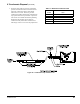
3. Temperature /Pressure Gauge Piping,
ALP080B through ALP210B Boiler Models
a. Locate and remove 1 in. NPT x 4 in. long black
nipple, 1 in. x 1 in. x 1 in. NPT black tee, 1
in. x ¼ in. NPT black reducing bushing and
Temperature & Pressure Gauge.
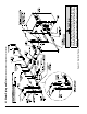
b. Mount the nipple into 1 in. boiler supply tapping
(see Figures 1A and 1B), then, install the tee onto
the nipple, making sure 1 in. branch outlet is in
horizontal plane and facing the boiler front.
c. Install 1 in. x ¼ in. NPT black reducing bushing
into the tee branch, then, put in Temperature &
Pressure Gauge.
4. Temperature /Pressure Gauge Piping,
ALP285B Boiler Model
a. Locate and remove 1¼ in. NPT x 2 in. long black
nipple, 1¼ in. x 1¼ in. x ¾ in. NPT black tee,
¾ in. x ¼ in. NPT black reducing bushing and
Temperature & Pressure Gauge.
b. Mount the nipple into 1¼ in. boiler supply
tapping (see Figures 1B and 1C), then, install
the tee onto the nipple, making sure ¾ in. branch
outlet is in horizontal plane and facing the boiler
front.
c. Install ¾ in. x ¼ in. NPT black reducing bushing
into the tee branch, then, put in Temperature &
Pressure Gauge.
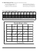
B. Piping System To Be Employed.
Alpine boilers are designed to operate in a closed loop
pressurized system. Minimum pressure in the boiler
must be 14.5 PSI (100 kPa). Proper operation of the
Alpine boiler requires that the water ow through the
boiler remain within the limits shown in Table 14, any
time the boiler is ring.
NOTICE
Failure to maintain the ow through boiler within
specied limits could result in erratic operation
or premature boiler failure.
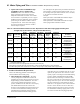
1. Near boiler piping must isolate ALP boiler
from system piping via closely spaced tees to
insure specied ow range through boiler any time
the boiler is ring:
a. The ow rate through the isolated near-boiler
loop is maintained by factory recommended and
installer supplied boiler circulator.
b. The ow rate through the isolated near-boiler
loop is completely independent of the ow rate
through the heating system loop(s).
c. The ow rate through the heating system loop(s)
is controlled by installer sized/provided system
loop circulator(s).
d. This piping arrangement can be used either for
space heating-only applications or space heating
with indirect water heater(s) applications.
i. Space heating only - refer to Table 13 and
Figure 21 “Near Boiler Piping - Heating
Only” as applicable.
ii. Space heating plus indirect water
heater(s) - refer to Table 13 and Figure 22
“Near Boiler Piping - Heating Plus Indirect
Water Heater” as applicable.
NOTICE
Where it is not possible to install a separate
boiler loop, the system circulator must be
sized to ensure that the ow through boiler
stays within the dened parameters to prevent
overheating when the boiler is red at it’s full
rated input. Install a ow meter to measure the
ow, or re the boiler at full rate and ensure the
boiler DT does not exceed 35°F (19°C).
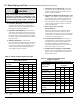
2. Direct connection of Alpine boiler to heating
system
, similar to a conventional boiler, is NOT
RECOMMENDED because:
a. The ow rate through system must be the same
as through boiler and fall within limits specied
in Table 14.
b. Pressure drop through entire system must be
known, added to pressure drop through boiler,
and, a circulator selected to provide required
ow at total calculated pressure drop.
VI. Water Piping and Trim B. Piping System To Be Employed (continued)