
Install Instructions


56 103448-08- 9/16
Boiler
Model
Boiler
Supply
Connection,
Inch, FPT
Boiler
Return
Connection,
Inch, FPT
Minimum
Required
Flow (GPM)
@ 35°F ΔT
Boiler
Head Loss,
Ft.
@ 35°F ΔT
Required
Flow,
(GPM)
@ 30°F ΔT
Boiler
Head Loss,
Ft.
@ 30°F ΔT
Required
Flow,
(GPM)
@ 25°F ΔT
Boiler
Head Loss,
Ft.
@ 25°F ΔT
Maximum
Required
Flow (GPM)
@ 20°F ΔT
Boiler
Head Loss,
Ft.
@ 20°F ΔT
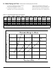
ALP080B 1 1 4.2 4.8 4.9 6.4 5.8 8.9 7.3 13.4
ALP105B 1 1 5.5 7.0 6.4 9.3 7.7 12.8 9.6 19.1
ALP150B 1 1 7.9 5.2 9.2 6.6 11.0 8.9 13.8 12.7
ALP210B 1 1 11.1 5.4 12.9 7.1 15.5 9.8 19.4 14.4
ALP285B 1¼ 1¼ 15.1 5.9 17.7 7.8 21.2 10.7 26.5 16.0
Notes: Required Flow (GPM) = ** Output (MBH) x 1000/500 x ΔT
** Output (MBH) - Select Value for specic Boiler Model from Table 2.
See also Table 13 for near boiler piping sizing. Using boiler
antifreeze will result in higher uid density and may require larger circulators.
Table 12: Flow Range Requirement Through Boiler
VI. Water Piping and Trim B. Piping System To Be Employed (continued)
c. It is often very difcult to accurately calculate
the pressure drop through the system.
d. In replacement installations, it may be nearly
impossible to get an accurate measurement of
piping amount and number of ttings in the
system. If system is zoned, the system ow rate
may drop well below recommended minimum
ow when only a single zone is calling for heat.
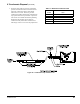
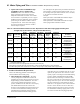
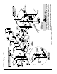
80
105
150
210
285
0
2
4
6
8
10
12
14
0 5 10 15 20 25
Pressure Drop (Feet of Head)
Flow Rate (GPM)
Pressure Drop vs. Flow