
Install Instructions

103448-08 - 9/16 57
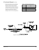
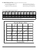
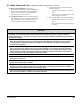
Table 13: Recommended Circulators for 50 ft. Equivalent ft. Near Boiler Piping [Approximately 20 ft.
Straight Pipe, (4) 90° Elbows, and (2) Full Port Ball Valves]
Boiler
Model
Boiler Supply
Connection,
Inch, FPT
Boiler
Return
Connection,
Inch, FPT
Near-Boiler
Piping
Supply Pipe
Size, Inch
Near-Boiler
Piping
Return Pipe
Size, Inch
Flow, GPM
@ 25°F
Temp.
Differential
Combined
Boiler &
Piping Loop
Head Loss, Ft.
Recommended
Circulator
Make & Model
ALP080B 1 1 1 1 7.3
(1)
14.7
Taco 0015 (Speed 3)
Grundfos UPS
15-58 (Speed 2)
ALP105B 1 1 1 1 7.7 14.3
Taco 0015 (Speed 3)
Grundfos UPS
26-99 (Speed 1)
ALP150B 1 1 1 1 11.0 11.7
Taco 0015 (Speed 3)
Grundfos UP
26-99 (Speed 2)
ALP210B 1 1 1¼ 1¼ 15.5 11.7
Taco 0014
Grundfos UP
26-99 (Speed 2)
ALP285B 1¼ 1¼ 1½ 1½ 21.5 12.3
Taco 0011
Grundfos UP
26-99 (Speed 3)
Notes:
(1)
Temperature Differential = 20°F
All Circulators shown are not equipped with internal ow check valve (IFC).
When selecting Circulators other than recommended, contact Circulator Manufacturer for sizing information.
Near-Boiler Piping Size shown is based on 2 to 5.5 Ft/Sec. velocity range to avoid potential noise and pipe erosion.
VI. Water Piping and Trim C. Standard Installation Requirements (continued)
The 10th digit of the Alpine boiler part number indicates the
brand of boiler circulator included with the boiler. A “T” in
the 10th digit of the part number indicates a Taco circulator;
a “G” indicates a Grundfos circulator.
Example:
Boiler part number: ALP105BW-2T02 indicates Alpine
boiler equipped with Taco Circulator
Boiler part number: ALP105BW-2G02 indicates Alpine
boiler equipped with Grundfos Circulator
C. Standard Installation Requirements
Observe the following guidelines when making the
actual installation of the boiler piping:
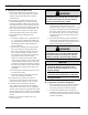
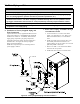
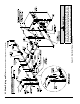
1. Safety Relief Valve (Required) - The relief
valve is packaged loose with boiler and must be
installed in the location shown in Figure 20 “Factory
Supplied Piping and Trim Installation”. The relief
valve must be installed with spindle in vertical
position. Installation of the relief valve must comply
with ASME Boiler and Pressure Vessel Code,
Section IV. The standard factory shipped relief valve
is rated for 30 PSI maximum working pressure for
ALP080B through ALP285B. Optional 50 PSI,
80 PSI and 100 PSI maximum working pressure
rated relief valves are available. If the valve is to be
replaced, the replacement valve must have a relief
capacity equal or exceeding the boiler DOE Heating
Capacity (models ALP080B through ALP285B).
Pipe the relief valve discharge to a location where
hot water or steam will not create hazard or property
damage if the valve opens. The end of the discharge
pipe must terminate in an unthreaded pipe. If the
relief valve is not piped to a drain, it must terminate
at least 6” above the oor. Do not run relief valve
discharge piping through an area prone to freezing.
The termination of discharge piping must be in an
area where it will not become plugged by debris.
3. Alpine boiler models ALP080B through
ALP285B are
factory supplied with
circulators,
which were sized for near-boiler
piping equivalent length of 50 ft. and listed
temperature differential. See Table 13 for details.
It is the installer’s responsibility to insure a proper
installation and where applicable, proper circulator
speed setting for the boiler circulator to achieve
a required ow rate. Where near-boiler piping
exceeds 50 equivalent feet, alternate circulator
selection may be required.