
Install Instructions

58 103448-08- 9/16
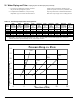
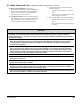
Table 14: Fitting and Valve Equivalent Length
Copper Fitting and Sweat Valve
Equivalent Length (Ft)
Fitting or Valve
Description
Copper Pipe or Valve Size
1 1¼ 1½ 2
90° Elbow 2.5 3.0 4.0 5.5
45° Elbow 1.0 1.2 1.5 2.0
Tee (through ow) 0.5 0.6 0.8 1.0
Tee (Branch ow) 4.5 5.5 7.0 9.0
Diverter Tee (typical) 23.5 25.0 23.0 23.0
Gate Valve 0.3 0.4 0.5 0.7
Globe Valve 25.0 36.0 46.0 56.0
Angle Valve 5.3 7.8 9.4 12.5
Ball Valve (standard port) 4.3 7.0 6.6 14.0
Ball Valve (full port) 1.9 1.4 2.2 1.3
Swing Check Valve 4.5 5.5 6.5 9.0
Flow-Check Valve
(typical)
54.0 74.0 57.0 177.0
Buttery Valve 2.7 2.0 2.7 4.5
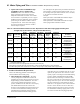
Threaded Fitting and Valve Equivalent Length (Ft)
Fitting or Valve
Description
Black Threaded Pipe or
Valve Size
1 1¼ 1½ 2
90° Elbow 2.6 3.5 4.0 5.2
Long Radius
Elbow (45° or 90°)
1.4 1.8 2.2 2.8
Tee (through ow) 1.8 2.3 2.7 3.5
Tee (Branch ow) 5.3 6.9 8.1 10.0
Close Return Bend 4.4 5.8 6.7 8.6
Gate Valve (full open) 0.7 0.9 1.1 1.4
Globe Valve (full open) 30.0 39.0 46.0 59.0
Angle Valve (full open) 13.0 17.0 20.0 26.0
Swing Check Valve
(full open)
8.7 12.0 13.0 17.0
Flow-Check Valve
(typical)
42.0 60.0 63.0 83.0
Table 14: Fitting and Valve Equivalent
Length (continued)
NOTE: Table 14 is provided as reference to assist in piping design and species equivalent length of typical piping ttings and
valves.
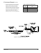
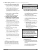
VI. Water Piping and Trim C. Standard Installation Requirements (continued)
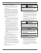
CAUTION
Burn Hazard. Safety relief valve discharge
piping must be piped such that the potential of
severe burns is eliminated. DO NOT pipe in any
area where freezing could occur. DO NOT install
any shut-off valves, plugs or caps. Consult local
codes for proper discharge piping arrangement.
2 Circulator (Required) – Usually at least two
circulators will be required to properly install a
Alpine™ Series boiler. See Paragraph B above for
information on sizing the circulators.
3. Expansion Tank (Required) – If this boiler is
replacing an existing boiler with no other changes
in the system, the old expansion tank can generally
be reused. If the expansion tank must be replaced,
consult the expansion tank manufacturer’s literature
for proper sizing.
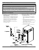
4. Fill Valve (Required) – Either manual
(recommended) or automatic ll valve may be used.
However, if automatic rell is employed, a water
meter must be added to evaluate the makeup water
volume taken after initial ll and eliminate any
water leakage as early as possible.
5. Automatic Air Vent (Required) –At least one
automatic air vent is required. Manual vents will
usually be required in other parts of the system to
remove air during initial ll.
6. Manual Reset High Limit (Required by some
Codes) – This control is required by ASME CSD-1
and some other codes. Install the high limit in the
boiler supply piping just above the boiler with no
intervening valves. Set the manual reset high limit
to 200°F. Wire the limit per Figures 27 and 28 in
Section VIII Electrical.
7. Flow Control Valve (Strongly
Recommended) –
The ow control valve prevents ow through the
system unless the circulator is operating. Flow
control valves are used to prevent gravity circulation
or “ghost ows” in circulator zone systems through
zones that are not calling for heat.
8. Y-strainer (Recommended) – A Y-strainer or
equivalent strainer removes heating system debris
from hydronic systems and protects boiler heat
exchanger from fouling up. Install the strainer
downstream of full port isolation valve, at the inlet
side of the circulator, for easy service.
9. Isolation Valves (Strongly recommended) –
Isolation valves are useful when the boiler must be
drained, as they will eliminate having to drain and
rell the entire system.