
Install Instructions


74 103448-08- 9/16
VIII. Electrical
A. General. Install wiring and electrically ground boiler
in accordance with requirements of authority having
jurisdiction or, in the absence of such requirements,
follow the National Electrical Code, ANSI/NFPA 70,
and/or Canadian Electrical Code Part 1, CSA C22.1
Electrical Code.
B. A separate electrical circuit must be run
from the main electrical service with an over-current
device/disconnect in the circuit. A service switch is
recommended and may be required by some local
jurisdictions. Install the service switch in the line
voltage “Hot” leg of the power supply. Locate the
IMPORTANT
This boiler is equipped with a feature that saves energy by reducing the boiler water temperature as the
heating load decreases. This feature is equipped with an override which is provided primarily to permit the
use of an external energy management system that serves the same function. THIS OVERRIDE MUST NOT
BE USED UNLESS AT LEAST ONE OF THE FOLLOWING CONDITIONS IS TRUE:
• An external energy management system is installed that reduces the boiler water temperature as
the heating load decreases.
• This boiler is not used for any space heating.
• This boiler is part of a modular or multiple boiler system having a total input of 300,000 BTU/hr or
greater.
• This boiler is equipped with a tankless coil.
DANGER
Electrical Shock Hazard. Positively assure all electrical connections are unpowered before attempting
installation or service of electrical components or connections of the boiler or building. Lock out all
electrical boxes with padlock once power is turned off.
WARNING
Electrical Shock Hazard. Failure to properly wire electrical connections to the boiler may result in
serious physical harm.
Electrical power may be from more than one source. Make sure all power is off before attempting any
electrical work.
Each boiler must be protected with a properly sized over-current device.
Never jump out or make inoperative any safety or operating controls.
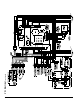
The wiring diagrams contained in this manual are for reference purposes only. Each boiler is shipped
with a wiring diagram attached to the front door. Refer to this diagram and the wiring diagram of any
controls used with the boiler. Read, understand and follow all wiring instructions supplied with the
controls.
NOTICE
This boiler is equipped with a high water temperature limit located inside the internal wiring of the
boiler. This limit provides boiler shutdown in the event the boiler water temperature exceeds the set
point of the limit control. Certain local codes require an additional water temperature limit. In addition,
certain types of systems may operate at temperatures below the minimum set point of the limit
contained in the boiler.
If this occurs, install an additional water temperature limit (Honeywell L4006 Aquastat). Wire as
indicated in the Electrical Section of this manual.
All wire, wire nuts, controls etc. are installer supplied unless otherwise noted.