
Install Instructions


103448-08 - 9/16 85
VIII. Electrical (continued)
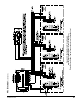
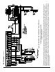
Figure 31B: Multiple Boiler Wiring Diagram w/Tekmar 264 Control
Tekmar 264 Based Control System (or equal)
Sequence of Operation
The Tekmar 264 Control (or equal) can control up to four (4) boilers and an Indirect Water Heater by utilizing stage ring. When a call for heat is received by the Tekmar 264
Control, the control will re either one or more boilers in sequential ring mode to establish a required reset water temperature in the system supply main based on outdoor
temperature. The boilers will modulate on their own based on each boiler’s Sage2.2™ Control and will target a setpoint temperature to supply enough input to the system
main to satisfy the desired reset water temperature in the main established by the Tekmar 264 Control. When a call for Indirect Hot Water is generated to the Tekmar 264,
the control will de-energize the zone pump control (ZC terminal), energize the Indirect pump and sequentially re the boilers to establish a setpoint temperature in the main
for the Indirect Heater using Priority. The Tekmar 264 Control will disable the stage ring and post purge the Indirect Pump to reduce the temperature in the Supply Main
near the end of the Indirect Mode to a point where it will need to be when it changes back to Space Heating Mode. The Tekmar 264 Control also has the ability to rotate the
lead-lag ring of the boilers to establish equal operating time for each boiler stage.