
Install Instructions


103448-08 - 9/16 91
1. Remove ue temperature sensor from vent
connector (see Figure 9) and insert combustion
analyzer probe through ue temperature sensor
silicon cap opening. If required, also remove
the ue temperature sensor silicon cap and insert
the analyzer probe directly into ue sensor port.
Reinstall the sensor and the cap upon combustion
testing completion.
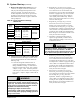
Boiler
Model
Altitude Range
0 - 7000 Ft.
% CO
2
% O
2
Range CO, PPM
ALP080B
9.9 - 8.2
(High Fire)
9.9 - 7.9
(Low Fire)
3.5 - 6.5
(High Fire)
3.5 - 7.0
(Low Fire)
Less than
100 PPM
ALP105B
ALP150B
ALP210B
ALP285B
Table 22: Typical Combustion Settings,
Natural Gas
IX. System Start-up (continued)
b. If high re O
2
is too low (CO
2
is too high),
increase O
2
(decrease CO
2
) by turning the throttle
screw clockwise in 1/4 turn increments and
checking the O
2
(or CO
2
) after each adjustment.
If boiler is equipped with 2 gas valves, throttle
screw adjustments must be done to both gas
valves equally and simultaneously. Refer to
Figure 37 for location of throttle screw. Verify
CO is less than 100 ppm.
c. If high re O
2
is too high (CO
2
is too low),
decrease O
2
(increase CO
2
) by turning the
throttle screw counter-clockwise in 1/4 turn
increments and checking the O
2
(or CO
2
) after
each adjustment. If boiler is equipped with 2 gas
valves, throttle screw adjustments must be done
to both gas valves equally and simultaneously.
Refer to Figure 37 for location of throttle screw.
Verify CO is less than 100 ppm.
d. Lock boiler in low re and allow boiler to
operate for approximately 5 minutes before
taking combustion readings. Press “Low” to
lock boiler in low re.
WARNING
Asphyxiation Hazard. Offset screw is adjusted
at the factory to the specication. DO NOT
touch the offset screw if measured low re O
2
(or
CO
2
) is within limits specied in Table 21 or 22.
e. If low re O
2
is too low (CO
2
is too high),
increase O
2
(decrease CO
2
) by turning offset
screw counterclockwise in less than 1/8 turn
increments and checking the O
2
(or CO
2
) after
each adjustment. If boiler is equipped with 2 gas
valves, offset screw adjustments must be done
to both gas valves equally and simultaneously.
Refer to Figure 37 for location of offset screw.
Verify CO is less than 100 ppm.
f. If low re O
2
is too high (CO
2
is too low),
decrease O
2
(increase CO
2
) by turning offset
screw clockwise in less than 1/8 turn increments
and checking the O
2
(or CO
2
) after each
adjustment. If boiler is equipped with 2 gas
valves, offset screw adjustments must be done
to both gas valves equally and simultaneously.
Refer to Figure 37 for location of offset screw.
Verify CO is less than 100 ppm.
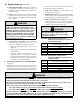
Boiler
Model
Altitude Range
0 - 7000 Ft.
% CO
2
% O
2
Range CO, PPM
ALP080B
11.4 - 9.5
(High Fire)
11.4 - 9.1
(Low Fire)
3.5 - 6.5
(High Fire)
3.5 - 7.0
(Low Fire)
Less than
100 PPM
ALP105B
ALP150B
ALP210B
ALP285B
Table 23: Typical Combustion Settings, LP Gas
2. Verify O
2
(or CO
2
) and CO are within limits
specied in Table 22 (natural gas) or Table 23 (LP
gas) at both high and low re as described in the
following steps.
a. Lock boiler in high re and allow boiler to
operate for approximately 5 minutes before
taking combustion readings. To lock boiler in
high re, from the home screen, press “Adjust”,
“Adjust”, “Login”, “000”. Enter the password
“086” and press return arrow to close the keypad.
Press “Save”, “Adjust”, “High” to lock boiler in
high re.
WARNING
Make sure that all adjustments at high re are
made with the throttle, not the offset screw (see
Figure 37). The offset screw has been factory set
using precision instruments and must never be
adjusted in the eld unnecessarily.
Attempting to adjust the offset screw
unnecessarily could result in damage to the gas
valve and may cause property damage, personal
injury or loss of life.