
Install Instructions


103448-08 - 9/16 93
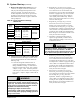
Table 24: Number of Clockwise Throttle
Screw Turns for LP Conversion
Boiler Model Gas Valve
Throttle Screw Turns at
Altitude Range
0 - 7000 Ft.
ALP080B
Dungs
GB-055
(½” NPT)
2¾
ALP105B 4
ALP150B 3¼
ALP210B 4
ALP285B
Dungs
GB-057
(¾” NPT)
4½
IX. System Start-up (continued)
P. Adjust Supply Water Temperature
As shipped, the heating set point supply temperature is
set to 180°F (82.2°C) and, indirect water heater set point
supply temperature is set to 170°F (76.7°C). If necessary,
adjust these to the appropriate settings for the type of
system to which this boiler is connected. See Section
X “Operation” (Parameter Table 29 on page 108) of this
manual for information on how to adjust supply setpoint.
Q. Adjust Thermostats
Adjust the heating and indirect water heater thermostats
to their nal set points.
R. Field Conversion From Natural Gas to LP
Gas
Alpine models ALP080 through ALP285 (-02, 27, 07
altitude code builds.) are factory shipped as natural gas
builds and can be eld converted to LP gas. Alpine
models ALP150, ALP210 and ALP285 (-70 altitude code
builds) are factory shipped as natural gas builds but are
not permitted to be eld converted to LP gas.
Follow steps below for eld conversion from natural gas
to LP Gas.
1. Conversion of Alpine models ALP080B through
ALP285B (-02, 27, 07 altitude code builds) from one
fuel to another is accomplished using the throttle screw
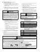
on the gas valve. Figure 37 “Gas Valve Detail” shows
the location of the throttle screw on the valve. Locate
the throttle screw on the boiler being converted.
WARNING
Explosion Hazard. Asphyxiation Hazard.
This conversion should be performed by a
qualied service agency in accordance with the
manufacturer’s instructions and all applicable
codes and requirements of the authority
having jurisdiction. If the information in these
instructions is not followed exactly, a re, an
explosion or production of carbon monoxide
may result causing property damage, personal
injury, or loss of life. The qualied service
agency is responsible for proper conversion of
these boilers. The conversion is not proper and
complete until the operation of the converted
appliance is checked as specied in this manual.
2. If conversion is being made on a new installation,
install the boiler in accordance with the installation
instructions supplied with the boiler. If an installed
boiler is being converted, connect the new gas supply
to the boiler, check for gas leaks, and purge the gas line
up to the boiler in accordance with the National Fuel
Gas Code, ANSI Z223.1/NFPA 54 and/or Natural Gas
and Propane Installation Code, CAN/CSA B149.1 or
the requirements of the authority having jurisdiction.
3. Before attempting to start the boiler, make the
number of turns to the throttle screw called for in Table
24.
4. Attempt to start the boiler using the Operating
Instructions located inside the lower front cover of
the boiler. If the boiler does not light on the rst try
for ignition, allow to boiler to make at least four more
attempts to light. If boiler still does not light, turn the
throttle counter clockwise in 1/4 turn increments,
allowing the boiler to make at least three tries for
ignition at each setting, until the boiler lights.
WARNING
Asphyxiation Hazard. The throttle adjustments
shown in Table 24 are approximate. The nal
throttle setting must be found using a combustion
analyzer. Leaving the boiler in operation with a
CO level in excess of the value shown in Table
23 could result in injury or death from carbon
monoxide poisoning.
Figure 37: Dungs Gas Valve Detail