
Install Instructions


103448-02 - 6/13 113
i. Fernox™ Protector Alphi 11 (combined
antifreeze and inhibitor).
Follow manufacturer application procedure
to insure proper antifreeze concentration and
inhibitor level.
Above referenced product is available from
Cookson Electronics Company, 4100 Sixth
Avenue, Altoona, PA 16602, Tel: (814) 946-
1611 and/or selected HVAC distributors.
Contact U.S. Boiler Company for specic
details.
b. Equivalent system freeze protection products
may be used in lieu of product referenced above.
In general, freeze protection for new or existing
systems must use specially formulated glycol,
which contains inhibitors, preventing the glycol
from attacking the metallic system components.
Insure that system uid contains proper glycol
concentration and inhibitor level. The system should
be tested at least once a year and as recommended by
the manufacturer of the glycol solution. Allowance
should be made for expansion of the glycol solution.
CAUTION
Use only inhibited propylene glycol solutions
specically formulated for hydronic systems.
Do not use ethylene glycol, which is toxic and
can attack gaskets and seals used in hydronic
systems.
E. Condensate Overow Switch and Condensate Trap
Removal and Replacement:
For removal or replacement of the condensate overow
switch and/or condensate trap follow the steps below. For
parts identication, refer to Section XIII “Repair Parts”.
1. Condensate Overflow Switch Removal and
Replacement:
a. Disconnect power supply to boiler.
b. Remove two (2) wire nuts and disconnect overow
switch wire pigtails from boiler wiring.
c. Using pliers, release spring clip securing the
overow switch to condensate trap body and remove
the switch. Note that the switch has factory applied
silicon adhesive seal, which may have to be carefully
cut all around to facilitate the switch removal.
d. Insure the trap overow switch port is not obstructed
with silicon seal debris, clean as needed.
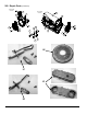
e. Apply silicon seal to the replacement switch
threads and install the switch into the trap body
making sure it is properly oriented - the arrow
molded into the switch hex end side must face
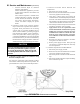
down for proper switch operation. See Figure
59 “Condensate Overow Switch Orientation”
for details.
f. Reconnect the switch wire pigtails to the boiler
wiring and secure with wire nuts.
g. Restore power supply to boiler. Fill up the trap
(see Section V “Condensate Disposal”) and verify
the switch operation.
2. Condensate Trap Removal and Reinstallation:
a. Disconnect power supply to boiler.
b. Remove two (2) wire nuts and disconnect overow
switch wire pigtails from boiler wiring.
c. Disconnect pressure switch hose from condensate
trap.
d. Disconnect outside condensate compression tting
from condensate trap stab.
XI. Service and Maintenance (continued)
Figure 59: Condensate Overow Switch Orientation