
Install Instructions


103448-02 - 6/13 19
IV. Venting
A. General Guidelines
1. Vent system installation must be in accordance
with National Fuel Gas Code, NFPA 54/ANSI
Z221.3 or applicable provisions of local building
codes. Contact local building or re ofcials about
restrictions and installation inspection in your area.
2. The Alpine™ is designed to be installed as a
Direct Vent (sealed combustion) boiler. The air
for combustion is supplied directly to the burner
enclosure from outdoors and ue gases are vented
directly outdoors (through wall or roof).
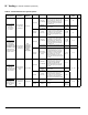
3. The following combustion air/vent system options
are approved for use with the Alpine™ boilers (refer
to Table 4):
a. Two-Pipe CPVC/PVC Vent/Combustion Air
System - separate CPVC/PVC pipe serves to
expel products of combustion and separate PVC
pipe delivers fresh outdoor combustion air.
Refer to Part B for specic details.
b. Two-Pipe Polypropylene Vent/Combustion Air
System - separate rigid or exible polypropylene
pipe serves to expel products of combustion and
separate rigid polypropylene pipe or PVC pipe
delivers fresh outdoor combustion air. Refer to
part C for specic details.
c. Two-Pipe Stainless Steel Vent/Combustion Air
System - separate stainless steel pipe serves to
expel products of combustion. Separate PVC or
galvanized pipe delivers fresh outdoor air. Refer
to Part C for specic details.
d. Concentric Inner Polypropylene Vent
and Outer Steel Combustion Air System
- the assembly consists of inner re resistant
polypropylene vent pipe and outer steel pipe
casing. The inner pipe serves as conduit to
expel products of combustion, while outdoor
fresh combustion air is drawn through the space
between the inner and outer pipes. Refer to Part
D for specic details.
4. Horizontal vent pipe must maintain a 1/4" per foot
slope down towards the boiler.
5. Horizontal combustion air pipe must maintain a
minimum ¼" per foot slope down towards terminal,
when possible. If not, slope toward boiler.
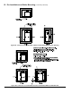
6. Do not install venting system components on
the exterior of the building except as specically
required by these instructions (refer to Figure 4):
a. Vent terminals must be at least 1 foot from door,
window, or gravity inlet into the building.
WARNING
Failure to vent this boiler in accordance with these instructions could cause products of combustion to
enter the building resulting in severe property damage, personal injury or death.
Do not interchange vent systems or materials unless otherwise specied.
The use of thermal insulation covering vent pipe and ttings is prohibited.
Do not use a barometric damper, draft hood or vent damper with this boiler.
When using the CPVC/PVC vent option, the use of CPVC is required when venting in vertical or horizontal
chase ways.
The CPVC vent materials supplied with this boiler do not comply with B149.1.S1-07 and are not ap-
proved for use in Canadian jurisdictions that require vent systems be listed to ULC S636-2008. In
these jurisdictions, vent this boiler using either stainless steel Special Gas vent or a listed ULC S636
Class IIB venting system.
Do not locate vent termination where exposed to prevailing winds. Moisture and ice may form on
surface around vent termination. To prevent deterioration, surface must be in good repair (sealed,
painted, etc.).
Do not locate air intake vent termination where chlorines, chlorouorocarbons (CFC’s), petroleum
distillates, detergents, volatile vapors or other chemicals are present. Severe boiler corrosion and
failure will result.
The use of cellular core PVC (ASTM F891), cellular core CPVC or Radel (polyphenolsulfone) is prohibited.
Do not locate vent termination under a deck.
Do not reduce specied diameters of vent and combustion air piping.
When installing vent pipe through chimney, as a chase, no other appliance can be vented into the
chimney.
Do not allow low spots in the vent where condensate may pool.