
Install Instructions


103448-02 - 6/13 25
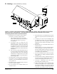
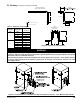
Figure 6: Field Installation of CPVC/PVC Two-Pipe Vent System Connector - Floor Mounted Boiler Builds
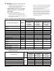
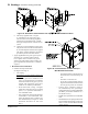
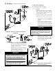
Figure 5: Expansion Loop and Offset
IV. Venting B. CPVC/PVC Venting (continued)
2 L
5
6"
MIN
6"
MIN
5
4
4
2
LONG RUN OF PIPE
CHANGE OF DIRECTION
(VERTICAL OR HORIZONTAL)
LOOP
(HORIZONTAL ONLY)
(TOP VIEW)
OFFSET
L
L
L
(L)
LOOP LENGTH
L
L
L
RESTRAINT (RESTRICTS MOVEMENT)
HANGER (ALLOWS MOVEMENT)
KEY
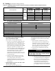
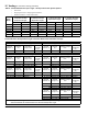
Nominal
Pipe Dia.
(In.)
Length of
Straight Run
(Ft.)
Loop Length
“L” (In.)
3
20 53
30 65
40 75
50 84
60 92
4
20 60
30 74
40 85
50 95
60 104
Table 7: Expansion Loop Lengths
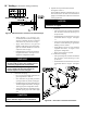
WARNING
Apply supplied silicon dielectric grease from attached pouch to gasket inside vent section of two-pipe vent
connector. Failure to apply the grease could result in gasket rupture during vent pipe installation and gasket
deterioration due to condensate exposure.
Check if ue exit gasket inside heat exchanger has factory applied silicon grease. If the gasket lubricant
is missing, apply supplied silicon dielectric grease prior to two-pipe vent connector insertion into heat
exchanger ue exit.