
Install Instructions


34 103448-02 - 6/13
IV. Venting C. Polypropylene Venting (continued)
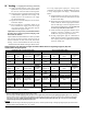
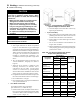
Vent/Combustion Air Equivalent Length Calculation Work Sheet for Rigid Polypropylene (PP) Vent
and Air Intake Two-pipe System
Notes:
Maximum listed exible polypropylene liner length is 48 feet.
Pressure drop for exible polypropylene pipe (liner) is 20% higher than pressure drop for rigid polypropylene pipe. When calculating
Total Equivalent Length for a particular venting application where exible polypropylene pipe (liner) is to be used in combination with straight
rigid polypropylene pipe, multiply projected measured length of exible polypropylene pipe (liner) by 1.2 to arrive at corresponding
equivalent length of straight rigid polypropylene pipe.
Example:
Projected measured length of exible polypropylene pipe (liner) is 35 feet. Equivalent length of straight rigid polypropylene pipe to be used for
Total Equivalent Length calculation is 35 * 1.2 = 42 feet
Combustion Air - Polypropylene (PP) Vent - Polypropylene (PP)
87° Elbow(s) PP (Installer Supplied) 87° Elbow(s) PP (Installer Supplied)
Nominal
Diameter, mm
Quantity
(Pc)
Equivalent
Length, Ft/Pc
Subtotal,
Equivalent
Ft. (A)
Nominal
Diameter, mm
Quantity
(Pc)
Equivalent Length,
Ft/Pc
Subtotal,
Equivalent Ft.
(A)
80 10 80 1 10
100
(110)
13
100
(110)
1 13
45° Elbow(s) PP (Installer Supplied) 45° Elbow(s) PP (Installer Supplied)
Nominal
Diameter, In.
Quantity
(Pc)
Equivalent
Length, Ft/Pc
Subtotal,
Equivalent
Ft. (B)
Nominal
Diameter, In.
Quantity
(Pc)
Equivalent Length,
Ft/Pc
Subtotal,
Equivalent Ft.
(A)
80 3.0 80 3.0
100
(110)
4.5
100
(110)
4.5
Straight Pipe, PP (Installer Supplied) Straight Pipe, PP (Installer Supplied)
Nominal
Diameter, In.
Quantity
(Length, Ft.)
Equivalent
Length, Ft/Ft
Subtotal,
Equivalent
Ft. (C)
Nominal
Diameter, In.
Quantity
(Length, Ft.)
Equivalent Length,
Ft/Ft
Subtotal,
Equivalent Ft.
(B)
80 1 80 1
100
(110)
1
100
(110)
1
* Total Equivalent Length, Ft. (A+B+C) =
* Total Equivalent Length, Ft. (A+B+C) + 2.5** =
** Add 2.5 ft (30”) Straight Pipe, CPVC (Supplied with Boiler)
if used)
11) Apply provided dielectric grease (grease pouch
taped to the vent system connector) all around to
the vent or air connection inner red silicon gasket.
12) Push and twist PVC to PP boiler adapter (ISAA0303
or ISAA0404 as applicable) into two-pipe vent
system connector vent connection or air supply
port until bottomed out.
13) Tighten the worm band clamp screw to secure PVC
to PP boiler adapter.
14) Do not install PVC to PP boiler adapter at the
lower combustion air supply port of the two-pipe
vent system connector when using PVC pipe for
combustion air supply to boiler.
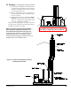
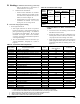
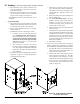
Alpine Boiler Two-Pipe Vent System Field Installation
Procedure To Accept Polypropylene Vent Piping – Wall
Mounted Boiler Builds:
Alpine wall mounted boiler builds have a factory installed
vent connector 90° elbow inside air box and air box top
located combustion air collar, See Part B ‘CPVC/PVC
Venting’, section ‘Field Installation of CPVC Vent Pipe
– Wall Mounted Boiler Builds’ and Figure 6B for details.
To accept polypropylene piping for venting and/or
combustion air (see Figure 15 “Field Installation Procedure
to accept Polypropylene Vent Piping – Wall Mounted
Boiler”
15) Install supplied 30” long CPVC pipe into a factory
installed vent connector 90° elbow and secure with
the elbow band clamp.
16) When using polypropylene pipe for combustion air
intake, install a 4” stub of an appropriate diameter
PVC air intake pipe (contractor supplied) onto air
box top located combustion air collar. Seal the stub
to air box top with silicon all around.
17) Attach and cement an appropriate diameter CPVC
coupling (contractor supplied) to previously
installed 30” long CPVC pipe exposed end.
18) If using polypropylene pipe for combustion air
intake, attach and cement an appropriate diameter
PVC coupling (contractor supplied) to exposed end
of PVC air intake stub.