
Install Instructions


103448-02 - 6/13 37
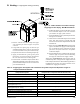
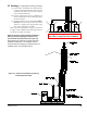
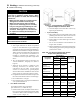
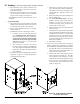
Figure 17: Field Installation of Two-Pipe Vent
System Adapter for Stainless Steel
IV. Venting D. Stainless Steel Venting (continued)
Vent System
Component
Part Numbers
Equivalent
Feet of Pipe
ALP080B -
210B
ALP285B -
399
3" Vent 4" Vent
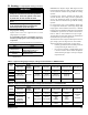
SS Vent Kit 102501-01 102501-02
N/A
Horizontal Vent
Terminal
(Included in Kit)
8116310 8116313
PVC to SS Vent
Adapter
(Included In Kit)
102219-01 102220-01
Vertical Vent Terminal 102680-01 102680-02 N/A
Pipe x 1 Ft. 8116296U 100176-01 1
Pipe x 3 Ft. 8116298U 100177-01 3
Pipe x 5 Ft. 8116300U 100178-01 5
Pipe x Adjustable 8116319U 100179-01
Equal to
Installed Length
(1.06 to 1.64)
90° Elbow 8116294U 100180-01
5.5 (3")
8.0 (4")
45° Elbow 8116292U 100181-01
4.0 (3")
4.5 (4")
Horizontal Drain Tee 8116302U 100182-01 2
Vertical Drain Tee 8116304U 100183-01 7½
Single Wall Thimble 8116116 100184-01 N/A
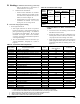
Table 13A: U.S. Boiler Company Vent System
Components (Stainless Steel)
D. Stainless Steel Venting
CAUTION
Vent systems made by Heat Fab, Protech and
Z-Flex rely on gaskets or proper sealing. When
these vent systems are used, take the following
precautions:
• Make sure that gasket is in position and un-
damaged in the female end of the pipe.
• Make sure that both the male and female
pipes are free of damage prior to assembly.
• Only cut vent pipe as permitted by the vent
manufacturer in accordance with their in-
structions. When pipe is cut, cut end must
be square and carefully de-burred prior to
assembly.
WARNING
All condensate that forms in the vent must be
able to drain back to the boiler.
1. Vent Length Restrictions
a. Vent length restrictions are based on equivalent
length of vent/combustion air pipe (total length
of straight pipe plus equivalent length of ttings).
Maximum vent/combustion air lengths are listed in
Table 8. Do not exceed maximum vent/combustion
air lengths. Do not include vent/combustion air
terminals in equivalent feet calculations. See
“Combustion Air/Vent, Equivalent Length Work
Sheet”.
b. The vent termination location is restricted as per
‘General Guidelines’, Paragraph A.5. (Refer to
Figure 4)
c. Where the use of “silicone” is called for in the
following instructions, use GE RTV 106 or
equivalent for the vent collar. Air inlet piping
sections are sealed with any general-purpose
silicone sealant such as GE RTV102. PVC air inlet
piping sections are connected with PVC cement.
d. Longitudinal welded seams should not be placed at
the bottom of horizontal sections of exhaust pipe.
e. Do not drill holes in vent pipe.
f. Do not attempt to mix vent components of different
vent system manufacturers.
2.
Near Boiler Connection
To install the stainless steel vent adapter
[P/N 102219-01 (3”). 102220-01 (4”)]:
a. Push the stainless steel vent adapter onto the CPVC/
PVC connector with a slight twisting motion. Make
sure that the stainless steel vent adapter is inserted
at least 1” (refer to Figure 17).
b. Secure the adapter to the CPVC/PVC connector by
tightening the metal strap.
3.
System Assembly
a. Plan venting system to avoid possible contact with
plumbing or electrical wires. Start at vent connector
at boiler and work towards vent termination.
b. Refer to Tables 13A and 13B for approved AL29C
Vent Systems.
c. Do not exceed maximum Vent/Combustion air
length. Refer to Table 8.
d. Follow all manufacturer instructions and warnings
when preparing pipe ends for joining and using the
primer and the cement.