
Install Instructions


38 103448-02 - 6/13
IV. Venting D. Stainless Steel Venting (continued)
e. Assemble the air intake system using either
galvanized or PVC pipe.
i. If PVC piping is used, use PVC cement to
assemble the PVC intake system components.
See Part B for air intake installation instructions.
ii. If galvanized piping is used, use at least two
sheet metal screws per joint. Seal the outside
of all joints.
4.
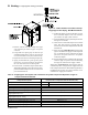
Horizontal Vent Termination
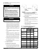
a. Standard Two-Pipe Termination
Refer to Figure 9A.
i. Vent Termination
• Use U.S. Boiler Company stainless
exhaust terminal [P/N 8110701 (3”), or
P/N 100184-01 (4”)]. The outer edge of
this terminal must be between 6” and 12”
from the surface of the wall.
The joint between the terminal and the
last piece of pipe must be outside of the
building.
• Male end of terminal will t into the female
end of any of the approved stainless vent
systems.
• Apply a heavy bead of silicone to the male
end of the terminal before inserting it into
the last piece of pipe. Orient the terminal
so that the seam in the terminal is at 12:00.
• Smooth the silicone over the seam between
the terminal and the last piece of pipe,
applying additional silicone if necessary
to ensure a tight seal.
• Allow the silicone to cure per the
silicone manufacturer’s instructions before
operating the boiler.
ii. Combustion Air Termination
• Horizontal intake terminal is a tee in the
upright position. Tee should protrude the
same distance from the wall as the exhaust
terminal. See Figure 9A.
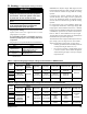
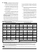
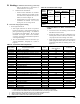
Manufacturer
Vent
System
Size Wall Thimbles Horizontal Termination
Vertical
Termination
Protech
Systems
Inc..
FasNseal
3 FSWT3 Tee: FSTT3 FSBS3
4 FSWT4 Tee: FSTT4 FSBS4
Z-Flex
SVE
Series III
(“Z-Vent III”)
3 2SVSWTEF03 Tee: 2SVSTTF03 24SVSTPF03
4 2SVSWTEF04 Tee: 2SVSTTF04 24SVSTPF04
Flex-L Intl. Star-34
3 SR03WT15 Tee: SRTT-03 SRTP-03
4 SR04WT15 Tee: SRTT-04 SRTP-04
NOTE: See vent system manufacturer’s literature for other part numbers that are required such as straight pipe, elbows, restops
and vent supports.
Table 13B: Alternate Vent Systems and Vent Components (Stainless Steel)
• Install a rodent screen (not supplied) in the
inlet terminal. Use a screen having 1/2”
(2 x 2) or larger mesh.
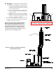
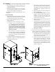
b. Optional Two-Pipe Snorkel Termination
Refer to Figure 11.
This installation will allow a maximum of seven
(7) feet vertical exterior run of the vent/combustion
air piping to be installed on the approved AL29C
Stainless Steel horizontal venting application.
i. Vent Termination
• After penetrating wall, install the
appropriate manufacturer’s 90° elbow so
that the elbow leg is in the up direction.
• Install maximum vertical run of seven (7)
feet of appropriate manufacturer’s vent
pipe. See Figure 11.
• At top of vent pipe length install another
appropriate manufacturer’s 90° elbow so
that the elbow leg is opposite the building’s
exterior surface.
• Install horizontal vent terminal.
• Brace exterior piping if required.
ii. Combustion Air Termination
• After penetrating wall, install a 90° elbow
so that the elbow leg is in the up direction.
• Install maximum vertical run of seven (7)
feet of combustion air pipe. See Figure 11.
• At top of vent pipe length install another
90° elbow os that the elbow leg is opposite
the building’s exterior surface.
• Install Rodent Screen (not supplied) and
horizontal vent terminal.
• Brace exterior piping if required.
5.
Vertical Vent Termination
a. Standard Two-Pipe Termination
Refer to Figures 12 and 13.
i. Vent Termination
• Use the terminal supplied by the vent
system manufacturer shown in Table 13B.