
Install Instructions


40 103448-02 - 6/13
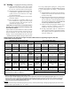
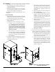
d. Flue temperature sensor, factory attached to the
boiler wiring harness, is secured to the left boiler
jacket panel with tape.
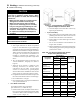
e. Remove the tape and push the sensor rubber plug
into Concentric Vent Collar sensor port until the
plug is securely engaged. See Figure 18.
The installation of the Concentric Vent Collar is now
completed.
3. System Assembly
a. Plan venting system to avoid possible contact with
plumbing or electrical wires. Start at vent connector
at boiler and work towards vent termination.
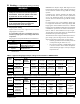
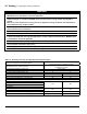
b. Do not exceed maximum Concentric vent length.
Refer to Table 14.
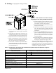
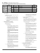
c. If additional concentric vent piping is needed:
i. Concentric Vent Cut-To-Length Extension
pipes, identied in Table 15 CAN BE CUT
to required length when used as an extension.
These pipes have plain male end and beaded
female end. Always cut the pipe from plain
male end. See Figure 19 ‘Cut-To-Length
Extension (Cuttable)”.
ii. The remaining Concentric Vent Fixed
Extensions shown in Table 15 CANNOT BE
CUT. These pipes have beaded male and beaded
female ends. See Figure 20 “Fixed Extension
(Non-Cuttable)’.
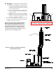
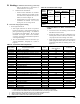
d. To cut the Concentric Vent Straight pipe to required
length refer to Figure 21 “Cutting Straight Pipe”
and the following procedure:
IV. Venting E. Concentric Polypropylene Venting (continued)
Figure 18: Field Installation of Boiler
Concentric Vent Collar
i. Determine the required length of the outer
pipe. When doing this allow an additional 1”
of length for insertion into the female end of
the adjoining pipe. Mark the cut line on the
outer pipe.
ii. Remove the plastic inner pipe by pulling it out
from the female end.
iii. Cut the OUTER PIPE ONLY at the point
marked in Step (a) using aviation shears, a
hacksaw, or an abrasive wheel cutter. Be
careful to cut the pipe square. De-burr the cut
end with a le or emery cloth.
iv. Make an insertion mark 1” from the male end
of the outer pipe.
v. Cut the plastic inner pipe so that it will protrude
3/8” beyond the male end of the outer pipe when
reinstalled in the outer pipe. Use a ne tooth
hacksaw or a PVC saw to cut the plastic pipe
and be careful to cut the pipe square. De-burr
the cut edge of the plastic pipe with a le, razor
blade or ne sandpaper.
vi. Reinstall the inner pipe.
e. To join Concentric Vent Pipe refer to Figure 22
“Joining Cuttable Pipe” and Figure 23 “Joining
Non-Cuttable Pipe” and follow the procedure below:
i. Start assembly of the vent system at the boiler.
Lubricate the brown gasket in the boiler vent
collar with a few drops of water.
ii. Push the male end of the rst tting into the
boiler collar until it bottoms out. The male
end of cuttable sections should go 1” into the
collar until the insertion mark (made in Step 4
above) is covered. On other ttings, the bead
on the male pipe will be bottom out on the
collar (see Figure 22).