
Install Instructions


44 103448-02 - 6/13
IV. Venting E. Concentric Polypropylene Venting (continued)
5.
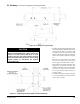
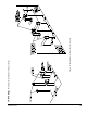
Vertical Vent Termination
a. Standard Concentric Termination
Refer to Figures 28 thru 32.
i. In addition to the vertical terminal, either a
Flat Roof Flashing or Sloped Roof Flashing
is required for this installation. Refer to Table
15 ‘Concentric Vent Components’ for details.
• Determine the centerline of the terminal
location on the roof. For at roof, cut 5½”
diameter hole (80/125 mm concentric vent
size) or 6½” (100/150 mm) for the terminal.
For sloped roof, cut a hole in the roof large
enough for the terminal to pass through the
roof while remaining plumb.
CAUTION
If the boiler is located directly under the hole,
cover it while cutting the hole to prevent debris
from falling onto boiler.
• Install the roof flashing using standard
practice on the roong system of the structure.
• If not already done, assemble the venting
system inside the building. The last section
of pipe needs to be on the same center line
as the terminal and within 19-1/4” of the top
edge of the roof ashing.
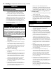
• Measure distance “H” from the top edge of
the storm collar to the end of the last tting
as shown in Figure 29.
• Add 1” to distance “H”. Carefully mark this
length on the pipe as shown in Figure 30.
• Cut the outer pipe only at the point marked
in Step (e) using aviation shears, a hacksaw,
or an abrasive wheel cutter. Be careful to cut
the pipe square. De-burr the cut end with a
le or emery cloth.
• Place a mark on the plastic inner pipe 3/8”
beyond the end of the outer pipe (Figure 30).
Use a ne tooth hacksaw to cut the plastic
pipe and be careful to cut the pipe square.
De-burr the cut edge of the plastic pipe with
a le or emery cloth.
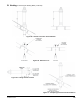
• Make a mark on the terminal section 1” from
the cut end of the outer pipe as shown in
Figure 30.
• Slip the terminal section through the roof
from the outside. Push into the last section
of vent pipe until the mark made in Step (h)
is not longer visible. Secure the terminal to
the last piece of pipe with three #10 x 1/2”
sheet metal screws. Drill a 1/8” hole through
both outer pipes to start these screws. Use a
drill stop or other means to ensure that
the drill bit does not penetrate more than
3/8” into the outer pipe. Do not use a sheet
metal screw longer than 1/2”.
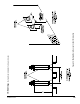
• Secure the terminal section to the inside of
the roof structure using the mounting bracket
provided with the terminal (Figure 31).
b. Optional Concentric Chimney Chase Installation
Refer to Figure 32.
i. A vertical concentric vent system can be
installed in an UNUSED masonry chimney.
• The Chimney chase Support Elbow with
attached Mounting Bracket is used at the base
of the chimney. Refer to Table 15 ‘Concentric
Vent Components’ for details. Slip the elbow
over the M10 x 35 screw in the support
bracket. Determine the desired vertical
location of the support elbow in the chimney
and mark the location of the pin, positioned
on the back of the support bracket, onto the
chimney rear wall. Drill a 7/16” diameter x
3-1/2” deep hole in the marked location, then,
insert the back bracket pin into the hole. The
front of the elbow mounting bracket should
be supported either by bottom of the opening
into chimney or installer supplied spacer.
• Construct a weather-tight at roof to cover
the top of the old chimney. Install the vertical
terminal through this roof using the at roof
ashing.
F. Removing the Existing Boiler
For installations not involving the replacement of an
existing boiler, proceed to Step F.
When an existing boiler is removed from a common venting
system, the common venting system is likely to be too large
for proper venting of the remaining appliances. At the time
of removal of an existing boiler, the following steps shall
be followed with each appliance remaining connected to
the common venting system placed in operation, while
the other appliances remaining connected to the common
venting system are not in operation:
1. Seal any unused openings in the common venting
system.
2. Visually inspect the venting system for proper size and
horizontal pitch and determine there is no blockage or
restriction, leakage, corrosion, and other deciencies
which could cause an unsafe condition.
3. Insofar as is practical, close all building doors and
windows and all doors between the space in which the
appliances remaining connected to the common venting
system are located and other spaces of the building.
Turn on clothes dryers and any appliance not connected
to the common venting system. Turn on any exhaust
fans, such as range-hoods and bathroom exhausts, so
they will operate at maxi mum speed. Do not operate
a summer exhaust fan. Close replace dampers.