
Install Instructions


60 103448-02 - 6/13
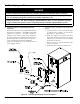
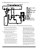
Figure 39: Isolation of the Boiler From Oxygenated Water with A Plate Heat Exchanger
VI. Water Piping and Trim E. Multiple Boiler Installation Water Piping (continued)
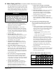
3. Boiler Piping with Air Handlers - Where the
boiler is connected to air handlers through which
refrigerated air passes, use ow control valves in the
boiler piping or other automatic means to prevent
gravity circulation during the cooling cycle.
E. Multiple Boiler Installation Water Piping – (See
Table 19 and Figures 40B and 41B)
1. Refer to this Section of this manual for:
a. Installation of Factory Supplied Piping and Trim
Components for an individual module (boiler).
b. Regarding an individual module (boiler) piping
system specic details.
c. Selection criteria for individual module (boiler)
space heating and/or DHW circulators.
2. For installations where indirect domestic hot water
heater is combined with space heating, when sizing
an indirect water heater circulator, compare the
specied ow range through an Alpine model boiler
to an indirect water heater (Alliance SL™) model
coil ow rate required to achieve water heater
rating. Refer to Table 20 and Figures 41A and 41B.
a. When Alliance SL™ model coil ow rate,
required to achieve water heater rating, falls
within the specied ow range for Alpine
boiler model, the Alliance SL™ model can be
piped as part of Alpine near-boiler piping.
Refer to Table 20 and Figures 41A and 41B.
b. When Alliance SL™ model coil ow rate,
required to achieve water heater rating,
exceeds the specied ow range for Alpine
boiler model, the Alliance SL™/Alpine boiler
combination may result in excessive noise and
boiler heat exchanger erosion, and therefore,
is not recommended. Refer to Table 20 and
Figures 41A and 41B for details.
c. When Alliance SL™ model coil ow rate,
required to achieve water heater rating, falls
below the specied ow range for Alpine boiler
model, the Alliance SL™ model must be piped
as a separate heating zone off the system
header. The circulator must be sized based on
the Alliance SL™ model coil ow and combined
coil pressure drop and the zone piping total
equivalent length. Refer to Table 20 and Figures
41A and 41B for details.