
Install Instructions


74 103448-02 - 6/13
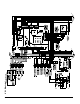
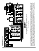
C. Refer to Figures 43 and 44 or details on the internal
boiler wiring.
Line Voltage (120 VAC) Connections - see Figure 43.
1. The line voltage connections are located in the
junction box on the left side of the vestibule. The
terminal block TB-1 in conjunction with terminal
screw identication label is attached to the junction
box combination cover/inside high voltage bracket.
2. The conductor insulation colors are:
a. Black – L1 line voltage “Hot”
b. White – L2 line voltage “Neutral” for boiler and
circulators
c. Red – Line voltage “Hot” for “Heating”
circulator, “System” circulator and “DHW”
circulator
d. Green – Ground connection
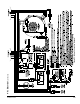
Low Voltage (24 VAC) Connections - see Figure 43.
3. The terminal block TB-2 in conjunction with
terminal screw identication label is attached to
the junction box front and located inside Control
compartment on the left side.
4. The connections are (listed identication label top to
bottom):
a. 1 – “Heating Thermostat”
b. 2 – “Heating Thermostat”
c. 3 – “DHW Temperature Switch”
d. 4 – “DHW Temperature Switch”
e. 5 – “Outdoor Sensor”
f. 6 – “Outdoor Sensor”
g. 7 – “Header Sensor”
h. 8 – “Header Sensor”
i. 9 – “Remote Firing Rate”
j. 10 – “Remote Firing Rate”
k. 11 – “External Limit”
l. 12 – “External Limit”
5. If the outdoor sensor is connected to terminals 5 and
6 “Outdoor Sensor”, the boiler will adjust the target
space heating set point supply water temperature
downwards as the outdoor air temperature increases.
If used, this sensor should be located on the outside
of the structure in an area where it will sense the
average air temperature around the house. Avoid
placing this sensor in areas where it may be covered
with ice or snow. Locations where the sensor will
pick up direct radiation from the sun should also
be avoided. Avoid placing the sensor near potential
sources of electrical noise such as transformers,
power lines, and uorescent lighting. Wire the
sensor to the boiler using 22 gauge or larger wire.
VIII. Electrical (continued)
Model Number
Nominal Current
(amps)
ALP080B <2
ALP105B <2
ALP150B <2
ALP210B <3
ALP285B <5
ALP399 <5
Table 25: Boiler Current Draw
D. Power Requirements
Nominal boilers current draw is provided in Table
25. These values are for planning purposes only
and represent only the boiler’s power consumption.
To obtain total system power consumption add any
selected circulator and component current draws.
E. Multiple Boiler Wiring
Install over-current protection in accordance with
authority having jurisdiction or, in the absence of such
requirements, follow the National Electric Code, NFPA
70, and/or CSA C22.1 Electrical Code. Do not provide
over-current protection greater than 15 amperes. If it
becomes necessary to provide greater amperes (because
of the number of boilers provided) use separate circuits
and over-current protection for additional boilers.
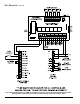
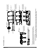
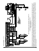
F. External Multiple Boiler Control System
As an alternate to the Control internal sequencer,
the Control also accepts an input from an external
sequencer. Follow multiple boiler control system
manufacturer (Honeywell, Tekmar, etc.) instructions
to properly apply a multiple boiler control system.
The Tekmar Model 264 and Model 265 based control
wiring diagrams (Figure 47A and 47B) are provided as
examples of typical multiple boiler control systems.
As with the sensor, the sensor wiring should be
routed away from sources of electrical noise. Where
it is impossible to avoid such noise sources, wire
the sensor using a 2 conductor, UL Type CM, AWM
Style 2092, 300Volt 60°C shielded cable. Connect
one end of the shielding on this cable to ground.
WARNING
When making low voltage connections, make
sure that no external power source is present in
the thermostat or limit circuits. If such a power
source is present, it could destroy the boiler’s
Microprocessor Control. One example of an
external power source that could be inadvertently
connected to the low voltage connections is a
transformer in old thermostat wiring.