
Install Instructions


82 103448-02 - 6/13
VIII. Electrical (continued)
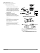
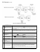
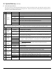
d. Multiple Boiler Setup
Step Description Comments
1
Install and wire the Header
Sensor
Wire the header sensor to low voltage terminal strip terminals “Header sensor”.
NOTE
This step can not be skipped. The Sequence Master can not be “enabled”unless a Header
Sensor is installed.
2
Install Ethernet Cables
between boilers
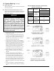
Standard Ethernet type cables with RJ45 connectors are “plugged in” to the Boiler-to-Boiler
Communication Network connection located on the side of the boiler. When more than two
boilers are connected an RJ45 splitter may be used to connect the boilers. Refer to Figure
50.
3 Apply Power to All Boilers
4
Set Unique Boiler
Addresses
Assign all boilers a unique Boiler Address using any number from 1 through 8.
WARNING
When two boiler’s addresses are the same undesirable simultaneous operation occurs.
5 Enable 1 Boiler Master
Enable only one Control’s Sequencer Master.
WARNING
When more than one Sequencer Master is enable erratic behavior will result.
6 Power Down All Boilers
7
Power Up Master
Sequencer
“Enabled” Boiler First
8 Power Up Other Boilers
9 Conrm Communication
From the Home Screen of the Control with the Master Sequencer “enabled”, select the Status
button. The Sequencer display shows the boiler address of the communicating boilers.
Additionally, from the “Home” screen select the “Detail” button and then the “Networked
Boilers” buttons to view boiler communication status.
If a boiler is not shown, check Ethernet cable connections and conrm all boilers have unique
addresses.
Figure 50: RJ45 Splitter Installation Detail