INSTALLATION, OPERATING AND SERVICE INSTRUCTIONS FOR ASPEN™ CONDENSING HIGH EFFICIENCY DIRECT VENT GAS - FIRED HOT WATER BOILER 9700609 Models: • ASPN-320 • ASPN-399 TO THE INSTALLER: Affix these instructions adjacent to boiler. TO THE CONSUMER: Retain these instructions for future reference. As an ENERGY STAR® Partner, U.S.
IMPORTANT INFORMATION - READ CAREFULLY NOTE: The equipment shall be installed in accordance with those installation regulations enforced in the area where the installation is to be made. These regulations shall be carefully followed in all cases. Authorities having jurisdiction shall be consulted before installations are made. All wiring on boilers installed in the USA shall be made in accordance with the National Electrical Code and/or local regulations.
WARNING Asphyxiation Hazard. Fire Hazard. Explosion Hazard. This boiler requires regular maintenance and service to operate safely. Follow the instructions contained in this manual. Improper installation, adjustment, alteration, service or maintenance can cause property damage, personal injury or loss of life. Read and understand the entire manual before attempting installation, start-up operation, or service.
Special Installation Requirements for Massachusetts A. For all sidewall horizontally vented gas fueled equipment installed in every dwelling, building or structure used in whole or in part for residential purposes and where the sidewall exhaust vent termination is less than seven (7) ft. above grade, the following requirements shall be satisfied: 1.
WARNINGS FOR THE HOMEOWNER FOLLOW ALL INSTRUCTIONS and warnings printed in this manual and posted on the boiler. unless alarms or other safeguards are in place to prevent such damage. MAINTAIN THE BOILER. To keep your boiler safe and efficient, have a service technician maintain this boiler as specified in Service and Maintenance Instructions. DO NOT BLOCK AIR FLOW into or around the boiler. Insufficient air may cause the boiler to produce carbon monoxide or start a fire.
Table of Contents I. Product Description II. Specifications 7 7 III. Before Installing IV. Locating The Boiler 10 V. Mounting The Boiler 12 Air For Ventilation 15 VII. Venting A. Vent System Design B. Design Requirements Unique to Horizontal Twin Pipe Venting Systems C. Design Requirements Unique to Vertical Venting Systems D. Design Requirements Unique to Split Vent Systems E. Assembly of CPVC/PVC Vent Systems F. Assembly of DuraVent PolyPro Vent Systems G.
I. Product Description This boiler is a stainless steel gas fired condensing boiler designed for use in forced hot water heating systems requiring supply water temperatures of 180°F or less. It is designed for installation on a floor or wall. This boiler may be vented vertically or horizontally with combustion air supplied from outdoors. It is not designed for use in gravity hot water systems or systems containing significant amounts of dissolved oxygen.
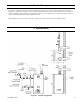
II. Specifications (continued) Figure 2.2: Boiler Internal Component Locations Table 2.3: Specifications Model * Maximum Heating Gas Approx. Minimum Maximum AHRI Net Water Allowable Gross Thermal Water Connection Net Input Input Rating * Volume Working Output Efficiency Connection Size Weight (MBH) (MBH) (MBH) (Gallon) Pressure Size (WPT) (NPT) (lb.) (PSI) ASPN-320 32 320 304 264 95.0 7.0 1 1/2" 3/4" 270 80 ASPN-399 39.9 399 379 330 95.0 6.
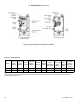
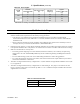
Table 2.4: Vent Lengths Model Size 320 399 II. Specifications (continued) Nominal Vent/Intake Size (in) Min Vent Length (in) Max Vent Length (ft) Approx. Derate at Max Vent (%) 3 30 60 8.2 4 30 135 3.7 3 30 50 5.3 4 30 135 2.9 See Section VII “Venting” for additional requirements and details. III. Before Installing 1.
III. Before Installing (continued) DANGER • Do not attempt to operate this boiler on LP gas without converting it using the proper conversion kit. • Do not attempt to convert this boiler to LP gas without the use of a combustion analyzer. • Failure to follow the conversion instructions will result in operation of the boiler at unsafe Carbon Monoxide (CO) levels and may result in personal injury or loss of life. Improper conversion may also result in unreliable operation, resulting in property damage.
IV. Locating the Boiler (continued) Figure 4.
V. Mounting The Boiler A. Wall Mounting CAUTION • Two people are required to safely lift this boiler onto the wall mounting hook. • Make sure that wall mounting hook is anchored to a structure capable of supporting the weight of the boiler and attached piping when filled with water. Jurisdictions in areas subject to earthquakes may have special requirements for supporting this boiler. These local requirements take precedence over the requirements shown below. 1.
V. Mounting The Boiler (continued) Figure 5.
V. Mounting The Boiler (continued) Figure 5.
VI . Air for Ventilation WARNING Outdoor combustion air must be piped to the air intake. Never pipe combustion air from areas containing contaminates such as swimming pools and laundry room exhaust vents. Contaminated combustion air will damage the boiler and may cause property damage, personal injury or loss of life. Air for combustion must always be obtained directly from outdoors. See Section VII “Venting” for intake piping.
VII. Venting WARNING Asphyxiation Hazard. Failure to vent this boiler in accordance with these instructions could cause products of combustion to enter the building resulting in severe property damage, personal injury or death. Do not interchange vent systems or materials unless otherwise specified. The use of thermal insulation covering vent pipe and fittings is prohibited. Do not use a barometric damper, draft hood or vent damper with this boiler.
VII. Venting A. Vent System Design (continued) Figure 7.0a: Horizontal Twin Pipe Figure 7.0b: Vertical Twin Pipe Figure 7.
1. VII. Venting A. Vent System Design (continued) Listed Vent Systems and Materials – The following materials and vent systems may be used to vent this boiler: • • • • • • • • CPVC – Use only CPVC listed to ASTM F441. In Canada, this pipe must also be listed to ULC S636. PVC – PVC may be used only as permitted in this manual. All PVC must be listed to ASTM D2665. At least 30" of CPVC pipe, and at least one CPVC elbow, must be installed between the boiler’s vent connection and the PVC pipe.
VII. Venting A. Vent System Design (continued) NOTICE Do not exceed maximum vent/combustion air system length. Refer to Tables 7.1 and 7.13 in this section for maximum vent/combustion air system length. Use only vent and combustion air terminals and terminal locations shown in Tables 7.5, 7.13, and 7.21 and related Figures in this section. 4. Minimum Vent and Air Intake Lengths - Observe the minimum vent lengths shown in Tables 7.5, 7.13 and 7.21. 5.
7. VII. Venting A. Vent System Design (continued) Supporting Pipe - Vertical and horizontal sections of pipe must be properly supported. Maximum support spacing is as follows: • • • • Support CPVC/PVC horizontally and vertically every 4 feet. Support DuraVent PolyPro horizontally near the female end of each straight section of pipe and vertically every 10 feet. Support Centrotherm InnoFlue horizontally every 39 inches with additional supports at elbows and vertically every 78".
VII. Venting A. Vent System Design (continued) Figure 7.3a Figure 7.3b Figure 7.3c Figure 7.3: Expansion Loops for CPVC/PVC Pipe Figure 7.
VII. Venting B. Design Requirements Unique to Horizontal Twin Pipe Venting Systems (continued) B. Design Requirements Unique to Horizontal Twin Pipe Venting Systems Table 7.5 summarizes all horizontal twin pipe vent options. Illustrations of horizontal twin pipe vent systems are shown in Figures 7.6 – 7.10. In addition to the requirements in Part VII-A, observe the following design requirements: 1.
VII. Venting B. Design Requirements Unique to Horizontal Twin Pipe Venting Systems (continued) Table 7.5: Summary of Horizontal Twin Pipe Venting Options Vent Option 7.6, 7.7, 7.8 1 7.6, 7.7, 7.8 3 4 5 6 7 8 7.9, 7.10 7.9, 7.10 7.9 7.9 7.9 7.
2. 24 VII. Venting B. Design Requirements Unique to Horizontal Twin Pipe Venting Systems (continued) Horizontal Vent and Air Intake Terminal Location - Observe the following limitations on the vent terminal location (also see Figure 7.11). When locating a concentric terminal, observe the limitations outlined below for “vent terminals”. • Vent terminal must be at least 1 foot from any door, window, or gravity inlet into the building.
VII. Venting B. Design Requirements Unique to Horizontal Twin Pipe Venting Systems (continued) Figure 7.7: Horizontal CPVC/PVC Venting with Low Profile Terminal, (Vent Options #1 & 2, Terminal Options B & C) Figure 7.
VII. Venting B. Design Requirements Unique to Horizontal Twin Pipe Venting Systems (continued) Figure 7.9: Duravent PolyPro, Selkirk, Polyflue or Centrotherm InnoFlue Horizontal Venting (Vent Option #3 - 8, Terminal Option A) 26 Figure 7.
107750-01 - 9/17 Figure 7.11: Location of Vent Terminal Relative to Windows, Doors, Grades, Overhangs, Meters and Forced Air Inlets - Two-Pipe System Vent Terminal (Shown) Two-Pipe System Air Intake Terminal (Not Shown) Note: Air intake termination not shown, refer to Venting Section in Installation Instructions supplied with the boiler. VII. Venting B.
VII. Venting C. Design Requirements Unique to Vertical Venting Systems (continued) Figure 7.12: Snorkel Terminal Configuration (CPVC/PVC Vent Systems Only) C. Design Requirements Unique to Vertical Venting Systems Table 7.13a summarizes all vertical twin pipe vent options. Table 7.13.b summarizes vent options in which an abandoned B-vent chimney is used both as a chase for the vent pipe and as a conduit for combustion air.
VII. Venting C. Design Requirements Unique to Vertical Venting Systems (continued) Table 7.13a: Summary of Vertical Twin Pipe Venting Options Option 10 11 12 13 14 15 16 17 7.15, 717 7.15, 7.17 7.17, 7.18 7.17, 7.18 7.17 7.17 7.17 7.
VII. Venting C. Design Requirements Unique to Vertical Venting Systems (continued) Table 7.13b: Summary of Vertical “B-Vent Air Chase” Vent Options (B-Vent Chase MUST Be Sealed) Option 18 19 20 21 7.19 7.19 7.20 7.
VII. Venting C. Design Requirements Unique to Vertical Venting Systems (continued) 2. Vertical Vent and Air Intake Location – Observe the following clearances from roof mounted terminals: • • • 3. Bottom of air intake opening must be at least 12" above the normal snow line anticipated on the roof. Exhaust opening must be at least 2ft above any portion of the roof or structure located within horizontally within 10ft.
VII. Venting C. Design Requirements Unique to Vertical Venting Systems (continued) Table 7.14: Equivalent Length of Flex Pipe Equivalent Length (ft) Flex Vent (1 ft): 3" DuraVent PolyPro Flex 2.0 ft 3" Centrotherm InnoFlue Flex 2.3 ft 3" Selkirk Polyflue 2.3 ft 3" DuraVent FasNSeal Flex 1.0 ft 4" DuraVent Poly Pro Flex 2.0 ft 4" Centrotherm InnoFlue Flex 2.3 ft 4" Selkirk Polyflue 2.3 ft 3" Flex Vent in 6" (or larger) B-Vent 1.0 ft 4" Flex Vent in 6" (or larger) B-Vent 1.
VII. Venting C. Design Requirements Unique to Vertical Venting Systems (continued) Figure 7.15: Vertical CPVC/PVC Venting (Vent Options 10 & 11, Terminal Option H) Figure 7.
VII. Venting C. Design Requirements Unique to Vertical Venting Systems (continued) Figure 7.17: Duravent PolyPro, Selkirk Polyflue or Centrotherm InnoFlue Vertical Single Wall PP Venting (Vent Options #12-17, Terminal Option H) Figure 7.
VII. Venting C. Design Requirements Unique to Vertical Venting Systems (continued) Figure 7.19: Duravent PolyPro B-Vent Air Chase System (Vent Options #18 & 19) Figure 7.
VII. Venting D. Design Requirements Unique to Split Vent Systems (continued) D. Design Requirements Unique to Split Vent Systems Table 7.21 summarizes all split vent options. Illustrations of split vent systems are shown in Figures 7.22, 7.23, and 7.24. In addition to the requirements in Part VII-A, observe the following design requirements: 1.
VII. Venting D. Design Requirements Unique to Split Vent Systems (continued) Example: A 399MBH model is to be installed as using Vent Option 34 in a masonry chimney as shown in Figure 7.23.
VII. Venting D. Design Requirements Unique to Split Vent Systems (continued) Table 7.21: Summary of Split Vent System Options Option # 25 Illustrated in Figure Pipe Penetration Through Structure Material Flex Termination & Components (B-Vent Chimney Chase) 28 29 30 7.22 7.22 7.22 7.22 7.22 7.
VII. Venting D. Design Requirements Unique to Split Vent Systems (continued) Table 7.21: Summary of Split Vent System Options (continued) Option # 31 Illustrated in Figure 32 33 34 7.22 7.22 7.23, 7.24 7.23, 7.
VII. Venting D. Design Requirements Unique to Split Vent Systems (continued) Table 7.21: Summary of Split Vent System Options (continued) Option # Illustrated in Figure Pipe Penetration Through Structure Material Vent Intake Vent Vent Intake Min Equivalent Vent Length: 320 Model Sizes 399 Max Equivalent Vent Length (Note 1): 320 Model Sizes 399 Rigid Vent Terminals Flex Termination & Components (Masonry Chimney Chase) (Note 3) Flex Termination & Components (B-Vent Chimney Chase) 36 37 38 39 40 7.
VII. Venting D. Design Requirements Unique to Split Vent Systems (continued) Figure 7.22: Split Rigid Vent System (Vent Options 25-32) Figure 7.
VII. Venting D. Design Requirements Unique to Split Vent Systems (continued) Figure 7.
VII. Venting D. Design Requirements Unique to Split Vent Systems (continued) WARNING Venting of Other Appliances (Or Fireplace) into Chase or Adjacent Flues Prohibited! Figure 7.
VII. Venting D. Design Requirements Unique to Split Vent Systems (continued) Figure 7.25a: Split Vent System (SS Flex in Abandoned Masonry Chimney) (Vent Option 39) WARNING Venting of Other Appliances (Or Fireplace) into Chase Prohibited! Figure 7.
VII. Venting E. Assembly of CPVC/PVC Vent Systems E. Assembly of CPVC/PVC Vent Systems WARNING Failure to follow this warning could result in asphyxiation and/or carbon monoxide poisoning. Correct venting material and installation is required for proper vent operation. PVC Vent Systems must include at least 30 inches of CPVC and one CPVC elbow between the boiler and PVC vent piping. See this Section, VII. Venting for complete information.
VII. Venting E. Assembly of CPVC/PVC Vent Systems (continued) Figure 7.26: Vent Connections and Flue Gas Sample Cap Location h. Maintain the clearances from the vent pipe outlined in Part VII-A of this manual. If exiting the exterior wall using PVC pipe, use half of an appropriately sized wall thimble (or a sheet metal plate) on the exterior of the building, to provide a weather tight seal while maintaining the proper clearance in the wall penetration.
VII. Venting E. Assembly of CPVC/PVC Vent Systems (continued) Figure 7.27: Installation of Standard Horizontal Terminals Figure 7.
4. 5. 6. 7. VII. Venting E. Assembly of CPVC/PVC Vent Systems (continued) Installation of Vertical Fitting Terminals (Terminal Option H): a. See Figure 7.28 for the proper orientation of twin pipe vertical terminals. b. The coupling is used to secure the rodent screen to the end of the vent pipe. c. A 180° bend (or two 90° elbows) are installed on the top of the air intake pipe. If two 90° elbows are used, the rodent screen provided can be installed between them (Figure 7.28).
VII. Venting E. Assembly of CPVC/PVC Vent Systems (continued) Figure 7.29: Installation of IPEX Low Profile Terminal Through Sidewall Figure 7.
VII. Venting E. Assembly of CPVC/PVC Vent Systems (continued) Figure 7.31: Cutting IPEX and Diversitech Concentric Vent Terminals Figure 7.
VII. Venting E. Assembly of CPVC/PVC Vent Systems (continued) Figure 7.33: Installation of IPEX and Diversitech Concentric Terminal Through Roof b. For vertical installations, cut a hole in the roof large enough to clear the concentric terminal at the location of the terminal (see Part VII-C of this manual for permitted terminal locations). c. If desired, the terminal can be shortened. See Figure 7.31 for specific information on making the terminal kit shorter based on the kit size being used.
VII. Venting F. Assembly of DuraVent PolyPro Vent Systems (continued) F. Assembly of DuraVent PolyPro Vent Systems 1. This boiler has been listed for use with the DuraVent PolyPro single wall PolyPropylene vent system to be provided by the installer. WARNING Asphyxiation Hazard. Follow these instructions and the installation instructions included by the original PolyPropylene venting component manufacturers, M&G/DuraVent.
VII. Venting F. Assembly of DuraVent PolyPro Vent Systems (continued) 3. Installation of Air Intake System - Start assembly of the PVC air intake system at the boiler. Assembly of the air intake system is done in the same manner as the vent system except as follows: a. Drill a 7/32" clearance hole into the front side of the air intake adapter.
VII. Venting F. Assembly of DuraVent PolyPro Vent Systems (continued) Figure 7.35: Installation of Duravent PolyPro UV Resistant Single Wall Horizontal Terminal Figure 7.
VII. Venting F. Assembly of DuraVent PolyPro Vent Systems (continued) 6. Installation of DuraVent PolyPro Horizontal Concentric Vent Terminal (Terminal Option D) Install PolyPro Horizontal Concentric Termination Kit #3PPS-HK or #4PPS-HK (Figure 7.38) as follows: a. At the planned location cut a 5-1/8" round hole for the 3" terminal or a 6-1/8" round hole for the 4" terminal in the exterior wall. (See Part VII-A of this manual for permitted terminal locations). b. If desired, the terminal can be shortened.
VII. Venting F. Assembly of DuraVent PolyPro Vent Systems (continued) Figure 7.38: Installation of Duravent PolyPro Concentric Vent Terminal Through Sidewall Figure 7.
VII. Venting F. Assembly of DuraVent PolyPro Vent Systems (continued) 8. Installations using PolyPro-flex (Vent Options 18,19,33,34): WARNING Asphyxiation Hazard. When using PolyPro flex, observe the following precautions: • PolyPro flex may be damaged by handling at low temperatures. Do not bend, uncoil, or attempt to install if it has been stored at a temperature below 42°F without allowing it to warm to a higher temperature first. • Do not bend PolyPro flex more than 45°.
VII. Venting G. Assembly of Selkirk Polyflue Vent Systems (continued) e. Support each pipe section as described in Polyflue manual at intervals not exceeding the following: Pipe size 3" 4" 3. Horizontal 39in 48in Vertical 16ft 16ft Installation of Air Intake System - Start assembly of the PVC air intake system at the boiler. Assembly of the air intake system is done in the same manner as the vent system except as follows: a.
VII. Venting G. Assembly of Selkirk Polyflue Vent Systems (continued) 6. Installations using flexible Polyflue (Vent Options 35,36): WARNING Asphyxiation Hazard. When using Polyflue flex, observe the following precautions: • Polyflue flex may be damaged by handling at low temperatures. Do not bend, uncoil or attempt to install if it has been stored at a temperature below 42°F without allowing it to warm to a higher temperature first. • Do not bend Polyflue flex more than 45°.
VII. Venting G. Assembly of Selkirk Polyflue Vent Systems (continued) Figure 7.41: Installation of Selkirk Polyflue UV Resistant Single Wall Horizontal Terminal Figure 7.
VII. Venting H. Assembly of Centrotherm InnoFlue Vent Systems H. Assembly of Centrotherm InnoFlue Vent Systems 1. This boiler has been listed for use with the Centrotherm InnoFlue single wall PolyPropylene vent system to be provided by the installer. WARNING Asphyxiation Hazard. Follow these instructions and the installation instructions included by the original PolyPropylene venting component manufacturers, Centrotherm.
VII. Venting H. Assembly of Centrotherm InnoFlue Vent Systems 3. Installation of Air Intake System - Start assembly of the PVC air intake system at the boiler. Assembly of the air intake system is done in the same manner as the vent system except as follows: a. Drill a 7/32" clearance hole into the front side of the air intake adapter.
VII. Venting H. Assembly of Centrotherm InnoFlue Vent Systems Figure 7.44: Installation of Centrotherm InnoFlue UV Stabilized Single Wall Horizontal Terminal Figure 7.
VII. Venting H. Assembly of Centrotherm InnoFlue Vent Systems 6. Installations using InnoFlue Flex (Vent Options 20,21,37,38): WARNING Asphyxiation Hazard. When using InnoFlue Flex, observe the following precautions: • InnoFlue Flex may be damaged by handling at low temperatures. Do not bend, uncoil or attempt to install if it has been stored at a temperature below 42°F without allowing it to warm to a higher temperature first. • Do not bend InnoFlue Flex more than 45°.
VII. Venting I. Assembly of Stainless Steel Vent Systems I. Assembly of Stainless Steel Vent Systems 1. This boiler has been listed for use with DuraVent FasNSeal Flex Stainless Steel vent systems to be provided by the installer. WARNING Asphyxiation Hazard. Follow these instructions and the installation instructions included by the original stainless steel venting component manufacturer, DuraVent.
VII. Venting I. Assembly of Stainless Steel Vent Systems (continued) d. When flexible stainless steel pipe is used for combustion product venting, it must be installed at vertical or near vertical orientation. This will insure proper condensate flow back towards the boiler. e.
VII. Venting J. Condensate Trap and Drain Line J. Condensate Trap and Drain Line All condensate which forms in the boiler or vent system passes through the heat exchanger and out of a bottom drain port which is connected to the field-installed condensate trap. This trap allows condensate to drain from the heat exchanger while retaining flue gases in the boiler. This trap is an integral part of the boiler but must be connected to a drain pipe as shown in Figure 7.48.
VII. Venting J. Condensate Trap and Drain Line (continued) Figure 7.47: Float Switch Connection to Wire Harness Figure 7.
VII. Venting K. Removing an Existing Boiler From a Common Chimney K. Removing an Existing Boiler From a Common Chimney This section only applies if this boiler is replacing an existing boiler that is being removed from a common chimney. In some cases, when an existing boiler is removed from a common chimney, the common venting system may be too large for the remaining appliances.
VIII. Gas Piping WARNING Explosion Hazard. Failure to properly pipe gas supply to boiler may result in improper operation or leaks of flammable gas. Gas supply to boiler and system must be absolutely shut off prior to installing or servicing boiler gas piping. Always assure gas piping is absolutely leak free and of the proper size and type for the connected load. Use a thread compound compatible with liquefied petroleum gas.
VIII. Gas Piping (continued) CAUTION Support the weight of the gas line piping independently from the boiler gas connection fitting located on the left side of the boiler. If an additional regulator is used to reduce boiler inlet pressure below 1/2 psig (3.5 kPa) it must be at least 6 to 10 ft. upstream of the boiler. It is very important that the gas line is properly purged by the gas supplier or utility company. Figure 8.1: Gas Connection to Boiler Table 8.
IX. System Piping A. General System Piping Precautions WARNING Failure to properly pipe boiler may result in improper operation and damage to boiler or structure. Install boiler so that the gas ignition system components are protected from water (dripping, spraying, rain, etc.) during boiler operation and service (circulator replacement, etc.). Oxygen contamination of boiler water will cause corrosion of iron and steel boiler components and can lead to boiler failure.
IX. System Piping (continued) B. Standard Piping Installation Requirements Observe the following requirements when installing the boiler piping: 1. Relief Valve (Required) – The relief valve is shipped loose and must be installed in the location shown in Figure 9.1. ASME Section IV currently requires that this relief valve be installed above the heat exchanger as shown.
IX. System Piping (continued) B. Standard Piping Installation Requirements (continued) 11. Low Water Cut-off (may be required by local jurisdiction) • Auto Reset Low Water Cut-off: Kit (P/N 105591-01) is available. Alternatively, use Hydrolevel Safgard 1100, Taco LTR Series or equivalent. • Manual Reset Low Water Cut-off: Kit (P/N 108182-01) is available. Alternatively, use Hydrolevel Safgard 1100M. LWCO plugs into the low voltage wire harness (refer to Section X "Wiring").
IX. System Piping (continued) Figure 9.2: LWCO Location C. Near Boiler Piping Design Proper operation of this boiler requires that the water flow rate through it remain within the limits shown in Table 9.3 any time the boiler is firing. At flow rates below the minimum shown, the boiler’s temperature rise limit function may prevent the boiler from firing. Flow rates through the boiler in excess of the maximum shown in Table 9.3 can result in excessive noise or erosion damage to piping.
IX. System Piping (continued) Method 1: Primary/Secondary Piping (Strongly Recommended) This method can be used in heat-only applications as shown in Figure 9.7a or with an indirect water heater as shown in Figure 9.7b, 9.7c. In this system, the flow rate through the boiler (“secondary loop”) is completely independent of the flow rate through the system (“primary loop”). Use the following guidelines to ensure that the boiler will have the required flow shown in Table 9.
107750-01 - 9/17 77 1 1/2 1 1/2 17.0 21.2 1.8 2.8 0010 0010 19.8 24.7 2.4 3.8 0010 0014 23.8 29.7 1 1/2 1 1/2 ASPN-320 ASPN-399 Boiler Model 21.2 17.0 2.8 1.8 Minimum Boiler & Pipe Flow Piping Size (GPM) Head Loss (in.) (ft) UPS26-99FC (Spd. 2) MAGNA1 3260F UPS26-99FC (Spd. 2) MAGNA1 3260F Circulator Model ∆T = 35°F 24.7 19.8 3.8 2.4 UPS26-99FC (Spd. 2) MAGNA1 3260F UPS26-99FC (Spd.
IX. System Piping (continued) 3. Indirect Water Heater Loop Piping – If an indirect water heater is used, install it as shown in Figure 9.7b, 9.7c. Refer to the indirect water heater installation manual for the proper sizing the indirect water heater loop pump and piping. 4. Hydraulic Separators – Hydraulic separators serve the same purpose as the closely spaced tees connecting the boiler and system loops.
107750-01 - 9/17 79 CAUTION: It is the installers responsibility to select boiler piping configurations that provide the proper flow rates and performance for the boiler. Figure 9.7a: Piping Method #1 - Near Boiler Piping; Heating Only HX Inlet Bottom Connection; HX Outlet Bottom Connection IX.
Figure 9.7b: Piping Method #1 - Near Boiler Piping - Heating Plus Supply Piped Indirect Water Heater HX Inlet Bottom Connection; HX Outlet Bottom Connection It is the installers responsibility to select boiler piping configurations that provide the proper flow rates and performance for the boiler and indirect water heater. CAUTION: IX.
107750-01 - 9/17 81 It is the installers responsibility to select boiler piping configurations that provide the proper flow rates and performance for the boiler and indirect water heater. CAUTION: Figure 9.7c: Piping Method #1 - Near Boiler Piping - Heating Plus System Piped Indirect Water Heater HX Inlet Bottom Connection; HX Outlet Bottom Connection IX.
IX. System Piping (continued) Method 2: Direct Connection to Heating System (Generally NOT Recommended) In some cases it may be possible to connect this boiler directly to the heating system as is done with conventional boilers (Figure 9.9). If this is done, the flow rate through the boiler will equal the flow rate through the system. The flow rate through the system must therefore always remain within the limits shown in Table 9.3. For this reason, the pressure drop through the entire system must be known.
IX. System Piping (continued) D. Piping for Special Situations 1. Systems containing oxygen - Many hydronic systems contain enough dissolved oxygen to cause severe corrosion damage to a this boiler. Some examples include: • Radiant systems that employ tubing without an oxygen barrier. • Systems with routine additions of fresh water. • Systems which are open to the atmosphere.
X. Wiring DANGER Electrical Shock Hazard. Positively assure all electrical connections are unpowered before attempting installation or service of electrical components or connections of the boiler or building. Lock out all electrical boxes with padlock once power is turned off. WARNING All wiring and grounding must be done in accordance with the authority having jurisdiction or, in the absence of such requirements, with the National Electrical Code /NFPA 70).
The use of the pump outputs are as follows: X. Wiring (continued) a. System Pump - Pumps water through the radiation. This pump is hydraulically separated from the boiler pump, either by closely spaced tees, or by a hydraulic separator. The system pump is always on when the system is responding to a call for CH. Depending on the DHW configuration, it may also be on during a call for DHW. b. DHW Pump (“IWH Circulator”) - Pumps water directly through the indirect water heater. c.
X. Wiring (continued) 120 VAC Connections Pump Fuse 120 V Line HOT GROUND DHW PUMP BOILER PUMP L N G L N L N L N System Pump DHW Pump Boiler Pump NEUTRAL Fuse 250 V 6.3 A Slow Blow 5x20mm Spare Pump Fuse OVERCURRENT PROTECTION/ DISCONNECT (BY INSTALLER) 120VAC/60HZ POWER SUPPLY SYSTEM PUMP Figure 10.2: High Voltage PCB Terminal Connections Low Voltage Connections Fuse F1 250 V 1.
X. Wiring (continued) With the exception of the alarm contacts, external power must not be applied to any of the low voltage terminals - doing so may damage the boiler control. Also note the following: a. External Limit - The external limit terminals are intended for use with a field supplied safety device, such as a manual reset high limit. When an external limit is used, the jumper between these two terminals must be removed.
X. Wiring (continued) Figure 10.
X. Wiring (continued) Figure 10.
107750-01 - 9/17 CONDENSATE FLOAT SWITCH X.
107750-01 - 9/17 91 Figure 10.6: Internal Wiring Connections Diagram X.
X. Wiring (continued) HEATING THERMOSTATS PRIORITY OFF TACO SR504 (OR EQUIVALENT) ZONE 4 PRIORITY ON ZONE 1 ZONE 2 ZONE 3 ZONE 4 OFF FOUR ZONE SWITCHING RELAY WITH OPTIONAL PRIORITY 24 VAC POWER POWER ZONE 1 ZONE 2 ZONE 3 ZONE 4 120V RELAY X X END ZC ZR SWITCH ZONE 1 ZONE 2 ZONE 3 ZONE 4 POWER 120 VOLT CIRCULATORS INPUT FUSE 1 AMP REMOVE JUMPER Low Voltage Connections 120 VAC Connections Pump Fuse Fuse F1 250 V 1.
X.
XI. Start-Up and Checkout WARNING Completely read, understand and follow all instructions in this manual before attempting start-up. NOTICE Safe lighting and other performance criteria were met with the gas train assembly provided on the boiler when the boiler underwent the test specified in ANSI Z21.13. Use the following procedure for initial start-up of the boiler: 1. Verify that the venting, water piping, gas piping and electrical system are installed properly. 2.
XI. Start-Up and Checkout (continued) DANGER Asphyxiation Hazard. Failure to properly convert this boiler for use on LP Gas (propane) can cause unreliable operation at elevated carbon monoxide (CO) levels, resulting in personal injury or death.
11. XI. Start-Up and Checkout (continued) Start the boiler using the operating instructions on page 100. With the boiler powered up, and with no call for heat, the display should look like Figure 11.1a. Once a call for heat is present, it will look like Figure 11.1b. 12. The boiler should attempt to fire approximately 30 seconds after a call for heat appears.
Figure 11.2: Burner Flame WARNING • Do not attempt to operate this boiler on LP gas without converting it using the proper conversion kit. • Do not attempt to convert this boiler to LP gas without the use of a combustion analyzer. • Failure to follow the conversion instructions will result in operation of the boiler at unsafe Carbon Monoxide (CO) levels and may result in personal injury or loss of life. Improper conversion may also result in unreliable operation, resulting in property damage.
XI. Start-Up and Checkout (continued) 16. Perform a combustion test. Boilers are equipped with a screw cap in the vent adapter. Be sure to replace this cap when combustion testing is complete. Check CO2 (or O2) and CO at both high and low fire. Ensure the door panel is sealed before combustion readings are taken. The boiler may be temporarily locked into high or low fire as follows: a. b. c. d. e. f. g. h. i. j. k. Fire the boiler through any call for heat.
XI. Start-Up and Checkout (continued) WARNING Asphyxiation Hazard. Improper gas valve adjustments can result in unreliable operation, substantial property damage, personal injury or loss of life due to carbon monoxide (CO) poisoning. Observe the following precautions: • Do not attempt to adjust gas valve without a combustion analyzer. • Each boiler is tested at the factory and adjustments to the gas valve are normally not necessary when operating on natural gas at sea level.
XI.
XII. Operation IMPORTANT This boiler is equipped with a feature that saves energy by reducing the boiler water temperature as the heating load decreases. This feature is equipped with an override which is provided primarily to permit the use of an external energy management system that serves the same function.
XII. Operation (continued) 7. Warm Weather Shutdown (WWSD) Some boilers are used primarily for heating buildings, and the boilers can be automatically shutdown when the outdoor air temperature is warm. When outside air temperature is above the WWSD setpoint, this function will shut down the boiler, boiler and system pump. 8.
XII. Operation (continued) 5. Outdoor Air Reset If an outdoor temperature sensor is connected to the boiler and Outdoor Reset is enabled, the Central Heat setpoint will automatically adjust downwards as the outdoor temperature increases. When the water temperature is properly matched to heating needs there is minimal chance of room air temperature overshoot. Excessive heat is not sent to the room heating elements by “overheated” (supply water temperature maintained too high a setting) water.
XII. Operation (continued) 5. Boiler Mounted Limit Devices The control monitors individual limit devices: External Limit, Optional Low Water Cut-Off (LWCO), Blocked Vent Switch, and Condensate Float Switch. If any of these limits open the boiler will shut down and an open limit indication is provided. Additionally, the control monitors an air proving switch.
XII. Operation (continued) 5. Customized Sequences Normally, boilers are started and stopped in numerical order. However, custom sequences may be established to optimize the heat delivery. For example, in order to minimize boiler cycling, a large boiler may be selected to run first during winter months and then selected to run last for the remainder of the year. 6.
XII. Operation (continued) E. Boiler Sequence of Operation 1. Normal Operation Table 12.3: Boiler Sequence of Operation Status Screen Display Priority: Standby Status: Standby Description (burner Off, circulator(s) Off) Boiler is not firing and there is no call for heat, priority equals standby. The boiler is ready to respond to a call for heat. (burner Off, circulator(s) On) Priority: Central Heat Boiler is not firing.
XII. Operation E. Boiler Sequence Of Operation (continued) 2. Using The Display The Control includes a touch screen LCD display. The user monitors and adjusts boiler operation by selecting screen navigation “buttons” and symbols. The “Home Screen” and menu selections are shown below. When no selection is made, while viewing any screen, the display reverts to the “Home Screen” after 4 minutes.
XII. Operation E. Boiler Sequence Of Operation (continued) 3. Status Screens Boiler Status screens are the primary boiler monitoring screens. The user may simply “walk” though boiler operation by repeatedly selecting the right or left “arrow” symbol. These screens are accessed by selected the “Status” button from the “Home” screen. NOTE Only visible if Zone Panel is connected. Zone Panel 1 and 2 shown typical for 1 through 4. Figure 12.6: Status Screens Figure 12.
XII. Operation E. Boiler Sequence Of Operation (continued) 3. Status Screens (continued) Bargraph Screen i The bargraph screen presents measured values for easy comparison. An information screen provides monitoring of "Rate Demand To Fan" and "Fan Speed Feedback". These additional monitoring points are provided to help monitor blower performance. Pumping is a major part of any hydronic system.
XII. Operation E. Boiler Sequence Of Operation (continued) 3. Status Screens (continued) Zone Control Status Screens Zone Control Status Active zones are shown by bold & underlined numbers. Press the zone panel to view zone cycle counts. Reset Cycle To reset all zone Counts cycle counts press: i < Zone Control Status press for zone cycles > Screen provides status and a page links for up to four zone panels. Individual zone “on” status is shown by a bold zone number with a solid underscore.
XII. Operation E. Boiler Sequence Of Operation (continued) 5. Multiple Boiler Sequencer Screens When the Sequence Master is enabled the following screen is available: The Sequencer Status screen is selected by “pressing” “Status” button from the “Home” screen when Sequence Master is enabled.
XII. Operation (continued) F. Changing Adjustable Parameters Adjust Mode 1. Entering Adjust Mode The Control is factory programmed to include basic modulating boiler functionality. These settings are password protected to discourage unauthorized or accidental changes to settings. User login is required to view or adjust these settings: - - - Press the “Adjust” button on the “Home” screen.
XII. Operation F. Changing Adjustable Parameters (continued) 2. Adjusting Parameters (continued) The following pages describe the Control’s adjustable parameters. Parameters are presented in the order they appear on the Control’s Display, from top to bottom and, left to right.
XII. Operation F. Changing Adjustable Parameters (continued) 2. Adjusting Parameters (continued) WARNING Asphyxiation Hazard. Boiler type is factory set and must match the boiler model. Only change the boiler type setting if you are installing a new or replacement Control. The boiler type setting determines minimum and maximum blower speeds. Incorrect boiler type can cause hazardous burner conditions and improper operation that may result in PROPERTY LOSS, PHYSICAL INJURY OR DEATH.
XII. Operation F. Changing Adjustable Parameters (continued) Table 12.10: Parameters Changed Using the Boiler Type Parameter Selections: Control Service Part 107877-02 Altitude Model 2,001-6,000 ft.
XII. Operation F. Changing Adjustable Parameters (continued) Expected Heat Rate Adjustment Screens (HeatMatch Software) The Control is shipped with defaults that will provide improved operation. Adjustment is only required to optimize setup. The expected heat rate adjustment is used to better match boiler output to the home heating needs. After receiving a “call for heat” the Control first uses the expected heat rate value to set a maximum heat rate.
XII. Operation F. Changing Adjustable Parameters (continued) “Press” button to access the following parameters: Factory Setting Range / Choices Never, System Pump run pump for: Activates the system pump output according to selected function. Never: Pump is disabled and not shown on status screen. Any Demand, Any Demand: Pump Runs during any call for heat. Central Heat, No Priority, Central Heat, No Priority: Pump Runs during central heat, auxiliary heat and frost protection call for heat.
XII. Operation F. Changing Adjustable Parameters (continued) Example Pump Parameter selections: Single boiler with no Indirect Water Heater Parameter Selection: System pump = “Central Heat, Optional Priority” Boiler pump = “any demand” DHW pump = “never” Explanation: This piping arrangement only services central heat. When there is any demand both boiler and system pumps turn on.
107750-01 - 9/17 to select boiler piping configurations that provide the proper flow rates and performance for the boiler and indirect water heater. CAUTION: It is the installers responsibility Single Boiler with Supply Piped IWH, System and DHW Wired to Master When call for Domestic Hot Water is received the DHW pump is turned on and the boiler pump is turned on. This piping arrangement permits the system pump to run or not run when there is a domestic hot water call for heat.
XII. Operation F.
XII. Operation F.
XII. Operation F. Changing Adjustable Parameters (continued) “Press” button to access the following parameters: Factory Range / Choices Setting Parameter and Description 60°F to 190°F (16°C to 87.8°C) Central Heat Setpoint Target temperature for the central heat priority. Value also used by the outdoor air reset function. 10°F (5.6°C) 2°F to 25°F (1.1°C to 14°C) Central Heat Diff Above The boiler stops when the water temperature rises ‘Diff Above’ degrees above the setpoint.
XII. Operation F. Changing Adjustable Parameters (continued) “Press” button to access the following parameters: Factory Setting Range / Choices 180°F (82.2°C) 60°F to 190°F (16°C to 87.8°C) Parameter and Description Auxiliary Heat Setpoint Target temperature for the Auxiliary Heat priority. Value also used by the outdoor air reset function. 10°F (5.6°C) 2°F to 25°F (1.1°C to 14°C) Auxiliary Heat Diff Above The boiler stops when the water temperature rises ‘Diff Above’ degrees above the setpoint.
XII. Operation F. Changing Adjustable Parameters (continued) “Press” button to access the following parameters: Factory Setting Range / Choices Parameter and Description 170°F (76.7°C) 60°F to 190°F (16°C to 87.8°C) Domestic Hot Water Setpoint The Domestic Hot Water (DHW) Setpoint parameter is used to create a minimum boiler water temperature setpoint that is used when DHW heat demand is “on”. When the DHW heat demand is not “on” (the contact is open or not wired) this setpoint is ignored. 10°F (5.
XII. Operation F. Changing Adjustable Parameters (continued) “Press” Factory Setting Enabled button to access the following parameters: Range / Choices Enable Disable Parameter and Description Central Heat Outdoor Reset Enable If an outdoor sensor is installed and Outdoor Reset is Enabled, the boiler will automatically adjust the heating zone set point temperature based on the outdoor reset curve in Figure 12.13. The maximum set point is defined by the Central Heat Setpoint [factory set to 180°F (82.
XII. Operation F. Changing Adjustable Parameters (continued) “Press” Factory Setting Enabled button to access the following parameters: Range / Choices Enable Disable Parameter and Description Auxiliary Heat Outdoor Reset Enable If an outdoor sensor is installed and Outdoor Reset is Enabled, the boiler will automatically adjust the heating zone set point temperature based on the outdoor reset curve in Figure 12.13. The maximum set point is defined by the Central Heat Setpoint [factory set to 180°F (82.
XII. Operation F. Changing Adjustable Parameters (continued) Figure 12.13: Outdoor Reset Curve Central Heat Setpoint Heating Element Type Central Heat Setpoint Heating Element Type 180°F to 190°F (82.2°C to 87.8°C) Fan Coil 100°F to 140°F (37.8°C to 60°C) In Slab Radiant High Mass Radiant 160°F to 190°F (71.1°C to 87.8°C) Convection Baseboard Fin Tube Convective 130°F to 160°F (54.4°C to 71.1°C) Staple-up Radiant Low Mass Radiant 130°F to 160°F (54.4°C to 71.
XII. Operation F. Changing Adjustable Parameters (continued) “Press” Factory Setting Disable Boiler Piped Disabled 180 Secs 195°F (90.6°C) 70% 3 button to access the following parameters: Range / Choices Master Enable/Disable The Sequencer Master Enable/Disable is used to “turn on” the Multiple Boiler Controller. Warning! enable ONLY one Sequence Master. Indirect Water Heater (IWH) Boiler Piped Sequencer to respond to an Isolated DHW demand that is piped to a single boiler.
XII. Operation F. Changing Adjustable Parameters (continued) “Press” Factory Setting button to access the following parameters: Range / Choices Parameter and Description Central Heat Modulation Source This parameter enables the 4-20mA input to control firing rate and the thermostat input to control boiler on/off demand directly without using the internal setpoint.
XIII. Service and Maintenance Important Product Safety Information Refractory Ceramic Fiber Product WARNING The Service Parts list designates parts that contain refractory ceramic fibers (RCF). RCF has been classified as a possible human carcinogen. When exposed to temperatures above 1805°F, such as during direct flame contact, RCF changes into crystalline silica, a known carcinogen. When disturbed as a result of servicing, these substances become airborne and, if inhaled, may be hazardous to your health.
XIII. Service and Maintenance (continued) WARNING Asphyxiation Hazard. Fire Hazard. Explosion Hazard. This boiler requires regular maintenance and service to operate safely. Follow the instructions contained in this manual. Improper installation, adjustment, alteration, service or maintenance can cause property damage, personal injury or loss of life. Read and understand the entire manual before attempting installation, start-up operation, or service.
XIII. Service and Maintenance (continued) NOTICE Warranty does not cover boiler damage or malfunction if the following steps are not performed at the intervals specified. 1. Continuously: a. b. c. 2. Keep the area around the boiler free from combustible materials, gasoline and other flammable vapors and liquids. Keep the area around the combustion air inlet terminal free from contaminates. Keep the boiler room ventilation openings open and unobstructed. Monthly Inspections: a.
XIII. Service and Maintenance (continued) Figure 13.1: Disconnecting Flexible Gas Line Figure 13.
XIII. Service and Maintenance (continued) i. Unplug the igniter, ground, and flame sensor wires from the ignition electrode and the flame sensor (Figure 13.2). j. Use an 8mm wrench to remove blower from fire door (Figure 13.2). k. Use a 10 mm wrench to remove fire door to the heat exchanger (Figure 13.2). Carefully remove the door from the heat exchanger, being careful not to damage the refractory insulation on the inside of the door (see Refractory Warning on page 130) or the electrodes. l.
XIII. Service and Maintenance (continued) 0.177in±0.02 4.5mm±0.5 Figure 13.3: Igniter Gap Figure 13.
XIII. Service and Maintenance (continued) Refer Section VII “Venting” to re-assemble any vent system components that are disassembled during this inspection and for details on supporting, pitching, and terminating the vent system. t. u. v. Reconnect any wiring which has been disconnected. Inspect the hydronic system. Look for leaks and repair any found. If system contains antifreeze, or other additives, test and/or maintain them as directed by the additive manufacturer.
XIV. Troubleshooting WARNING Electrical Shock Hazard. Turn off power to boiler before working on wiring. A. Troubleshooting problems where no error code is displayed. Condition Possible Cause Boiler not responding to call for heat, “Status” and “Priority” show “Standby”. Boiler not responding to a call for heat, “Status” shows “Standby” and “Priority” shows Central Heat or Domestic Hot Water. Boiler is not seeing call for heat.
XIV. Troubleshooting (continued) C. Help Screen Faults Indication Condition Zone Panel 1 Setup Flashing Zone Panel Failure Zone Panel Setup Possible Cause Zone Panel 1 communication lost, typical for Panel 1 through 4: The zone panel’s communication was established and then lost. Check the following to correct the issue: • Wiring between panel and boiler.
XIV. Troubleshooting (continued) E. Active Fault Screen Faults Indication Condition Limit String Status Limit String Fault Sensor Status NOTE: Since the limit string items are wired in series, all limits downstream of the “open” limit will also appear on the screen as “open” (blinking) icons regardless of whether or not they are actually open. The Air Proving Switch is wired independent to all other limits. The Air Proving Switch is only required to be closed during boiler prepurge.
XIV. Troubleshooting (continued) F. Troubleshooting problems where a Soft Lockout Code is displayed. When a soft lockout occurs, the boiler will shut down, the display will turn red and the “Help” button will “blink”. Select the “blinking” “Help” button to determine the cause of the soft lockout. The boiler will automatically restart once the condition that caused the lockout is corrected.
XIV. Troubleshooting (continued) Soft Lockout Codes Displayed (continued) Lockout Number Condition 13 Flame rod • shorted to ground Flame rod shorted to ground 14 Differential Temperature rise between supply and return Temperature inlet/ is too high. outlet high The Control is reading a return sensor 15 temperature higher than the supply sensor Return temp temperature. Condition must be present for higher than supply at least 75 seconds for this error code to appear.
XIV. Troubleshooting (continued) G. Troubleshooting problems where a Hard Lockout Code is displayed. When a hard lockout occurs, the boiler will shut down, the display will turn red and the “Help” button will “blink”. Select the “blinking” “Help” button to determine the cause of the Hard Lockout. Once the condition that caused the lockout is corrected, the boiler will need to be manually reset using the Reset button on the “Active Fault” display or located on the Control.
XV. Service Parts All ASPEN™ Series Service Parts may be obtained through your local U.S. Boiler Wholesale distributor. Should you require assistance in locating a U.S. Boiler distributor in your area, or have questions regarding the availability of U.S. Boiler products or service parts, please contact U.S. Boiler Customer Service at (717) 481-8400 or Fax (717) 481-8408.
XV. Service Parts (continued) Space Heating Models Heat Exchanger and Piping Service Parts Key No. 144 Description 1A Heat Exchanger Part Number (Qty) ASPN-320 ASPN-399 Contact U.S. Boiler Company. Provide boiler serial number.
XV.
XV. Service Parts (continued) All Models MBH Blower and Gas Train Service Parts Key No.
XV.
XV. Service Parts (continued) All Models Jacket Service Parts Key No.
XV.
XV. Service Parts (continued) All Models Control Panel Service Parts Part Number (Qty) Key No.
107750-01 - 9/17 151 All models XV.
XV. Service Parts (continued) 5C 5B 5A 5E 5D All Models Wire Harness Service Parts Key No.
Appendix A: Instructions for High Altitude Installations Above 2,000 ft. These instructions apply only to the following altitude ranges: 2001 - 6000, 6001 - 7800, 7801 - 10,100 These instructions contain specific information to setup your boiler to ensure proper operation. WARNING LP Conversions - boiler setup from factory is configured for use with natural gas installed from 0 - 2,000 ft. above sea level only. For conversion to LP, use a proper conversion kit per Table 3.1.
Appendix A - (continued) Table A.1: Altitude Adjustments (Above 2,000 ft. only) Model No. Fuel Approximate Derate per 1,000 ft. 2,001-6,000 ft 6,001-7,800 ft 7,801-10,1000 ft NG 0.3% ASPN-320 1.6% 0.0% LP 0.8% 2.1% NG 1.5% ASPN-399 0.6% LP 1.3% 3.9% De-rate’s per 1000 ft. are approximate Based on minimum vent length Table A.2: Acceptable Combustion Readings (Above 2000 ft. only) Measured CO2 (%)* Model No. Fuel 2,001-6,000 ft 6,001-7,800 ft Max.
Appendix B: Special Requirements For Side-Wall Vented Appliances In The Commonwealth of Massachusetts IMPORTANT The Commonwealth of Massachusetts requires compliance with regulation 248 CMR 4.00 and 5.00 for installation of side-wall vented gas appliances as follows: a.
Appendix B - (continued) 1. Detailed instructions for the installation of the venting system design or the venting system components; and 2. A complete parts list for the venting system design or venting system. d. MANUFACTURER REQUIREMENTS - GAS EQUIPMENT VENTING SYSTEM NOT PROVIDED.
107750-01 - 9/17 157
107750-01 - 9/17
107750-01 - 9/17 159
U.S. Boiler Company, Inc. P.O. Box 3020 Lancaster, PA 17604 1-888-432-8887 www.usboiler.