
Install Instructions


104
107750-01 - 9/17
XII. Operation (continued)
5. Boiler Mounted Limit Devices
The control monitors individual limit devices: External
Limit, Optional Low Water Cut-Off (LWCO), Blocked
Vent Switch, and Condensate Float Switch. If any of
these limits open the boiler will shut down and an open
limit indication is provided. Additionally, the control
monitors an air proving switch. During the boiler start
sequence the control requires the air proving switch to
be in the “open” position before the blower starts and
in the “closed” position after the blower starts. If the
air proving switch is not in the required position the
start sequence is halted or the boiler is shut down and
the open limit indication is provided. The air proving
switch is only required to be closed during pre-purge.
It is normal for the air proving switch to be open during
run mode.
6. Stack High Limit
The Control monitors the ue gas temperature sensor
located in the vent connector. If the ue temperature
exceeds 194°F (90°C), the control begins to reduce the
maximum blower speed. If the ue temperature exceeds
204°F (96°C), a forced boiler recycle results. If the
ue temperature exceeds 214°F (101°C), the control
activates a manual reset Hard Lockout.
7. Flame Current Modulation Boost
To help prevent nuisance shutdowns when the boiler is
ring at minimum ring rates, the control will increase
the ring rate when the ame current is too low.
8. Ignition Failure
The Control monitors ignition using a burner mounted
ame sensor. In the event of an ignition failure, the
control retries 5 times and then goes into soft lockout
for one hour.
9. Central Heating System Frost Protection
When enabled, Frost Protection starts the boiler and
system pump and res the boiler when low outside air
and low supply water temperatures are sensed. The
Control provides the following control action when
frost protection is enabled:
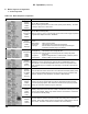
Table 12.2: Frost Protection
Device
Started
Start
Temperatures
Stop
Temperatures
Boiler Pump
Outside Air < 0°F (-18°C)
Supply Water < 45°F (7.2°C)
Outside Air > 4°F (-16°C)
Supply Water > 50°F (10°C)
Boiler Supply Water < 38°F (3.3°C) Supply Water > 50°F (10°C)
FROST PROTECTION NOTE
The Control helps provide freeze protection for the boiler
water. Boiler ue gas condensate drain is not protected from
freezing. Since the Control only controls the system and
boiler circulators individual zones are not protected. It is
recommended that the boiler be installed in a location that is
not exposed to freezing temperatures.
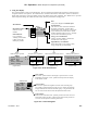
D. Multiple Boiler Control Sequencer
1. “Plug & Play” Multiple Boiler Control
Sequencer
When multiple boilers are installed, the Control’s
Sequencer may be used to coordinate and optimize
the operation of up to eight (8) boilers. Boilers are
connected into a “network” by simply “plugging in”
standard ethernet cables into each boiler’s “Boiler-To-
Boiler Communication” RJ45 connection.
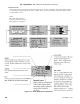
2. Sequencer Master
A single Control is parameter selected to be the
Sequencer Master. The call for heat, outdoor and
header sensors, and common pumps are wired to the
Sequencer Master “enabled” Control.
3. Lead/Slave Sequencing & Equalized Run Time
One boiler is a “Lead” boiler and the remaining
networked boilers are “Slaves”. When demand is
increasing, the Lead boiler is the rst to start and the
Slave boilers are started in sequential order (1,2,3,…)
until the demand is satised. When demand is
decreasing, the boilers are stopped in reverse order with
the Lead boiler stopped last (…,3,2,1). To equalize
the run time the sequencer automatically rotates the
Lead boiler after 24 hours of run time.
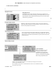
4. Improved Availability
The following features help improve the heat
availability:
a. Backup Header Sensor: In the event of a header
sensor failure the lead boiler’s supply sensor is used
by the Sequence Master to control ring rate. This
feature allows continued coordinated sequencer
control even after a header sensor failure.
b. “Stand Alone” Operation Upon Sequence Master
Failure: If the Sequence Master Control is powered
down or disabled or if communication is lost
between boilers, individual boilers may be setup
to automatically resume control as a “stand alone”
boiler.
c. Slave Boiler Rate Adjustment: Each slave boiler
continues to monitor supply, return and ue gas
temperatures and modies the Sequence Master’s
ring rate demand to help avoid individual boiler
faults, minimize boiler cycling and provide heat to
the building efciently.
d. Slave Boiler Status Monitoring: The Sequence
Master monitors slave boiler lockout status and
automatically skip over disabled boilers when
starting a new slave boiler.