
Install Instructions


36
107750-01 - 9/17
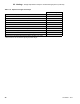
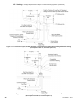
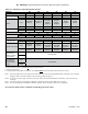
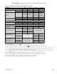
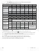
Table 7.21 summarizes all split vent options. Illustrations of split vent systems are shown in Figures 7.22, 7.23, and 7.24. In
addition to the requirements in Part VII-A, observe the following design requirements:
1. Permitted Terminals for Split Venting:
Rigid Vent Systems (Vent Options 25-32) – Vent terminates in a plain end (coupling for PVC, bell end for PolyPro, Polyue,
and plain end pipe for InnoFlue). Intake terminates in a PVC 90 sweep elbow pointing down. The section of PolyPro,
Polyue or InnoFlue exposed to the outdoors must be UV resistant.
Use of a rodent screen is generally recommended for the vent termination. A rodent screen suitable for 4" PVC terminals
is installed under the termination coupling as shown in Figure 7.27. Rodent screens (“bird guards”) for PolyPro, Polyue and
InnoFlue are as follows:
Size/Vent System Rodent Screen (“Bird Guard”)
3" PolyPro DuraVent # 3PPS-BG
4" PolyPro DuraVent # 4PPS-BG
3" Polyue Selkirk #3PF-HVST
4" Polyue Selkirk #4PF-HVST
3" InnoFlue Centrotherm # IASPP03
4" InnoFlue Centrotherm # IASPP04
Flex Vent Terminals (Options 33-39) – The ex vent kits shown for options 33-38 include vent terminals that must be
installed in accordance with the vent manufacturer’s instructions. Different terminals are used for Masonry and B-vent
chimney chases.
Air Intake Terminals (Vent Options 25-39) - All split venting options shown in Tables 7.21 terminate in a PVC 90 sweep
elbow pointing down. Use of a rodent screen is generally recommended for the intake termination. A rodent screen suitable
for 4" PVC terminals is installed under the intake termination elbow coupling as shown in Figure 7.27. If 3" CPVC is used,
this screen can be cut to t into the smaller tting.
2. Vent Terminal Location – Observe the following clearances from roof mounted vent terminals (also see Figures 7.22, 7.23, or
7.24):
• Bottom of terminal must be at least 12" above the normal snow line anticipated on the roof.
• Exhaust opening must be at least 2ft above any portion of the roof or structure located within horizontally within 10ft.
3. Horizontal Air Intake Terminal Location - Observe the following limitations on the intake terminal location (also see Figures
7.22, 7.23, or 7.24):
• The bottom of all terminals must be at least 12" above the normal snow line. In no case should they be less than 12"
above grade level.
• If possible, install the intake terminal on a wall away from the prevailing wind. Reliable operation of this boiler cannot
be guaranteed if the intake terminal is subjected to winds in excess of 40 mph.
• Air intake terminal must not terminate in areas that might contain combustion air contaminates, such as near swimming
pools. See WARNING on page 15.
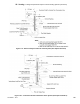
4. Use of abandoned chimneys as a vent chase (Options 33-38) – Vent options 33-38 permit exible PolyPropylene venting
to be routed to the roof using an abandoned masonry or B- vent chimney. In these applications combustion air is drawn
horizontally from a wall terminal. See Figure 7.23 or 7.24. When using one of these vent options, observe the following
requirements:
• When a masonry chimney containing multiple ues is used as a chase, ALL ues must be abandoned (Figure 7.26).
• Masonry or B vent chimney used as a chase must be structurally sound.
• Use of ex PolyPropylene outside of a masonry or B-vent chimney is not permitted unless allowed by the vent
manufacturer and permitted by local codes.
• All venting is PolyPropylene supplied by the vent manufacturer shown in Table 7.21. The portion of this venting within
the masonry or B–vent chimney is exible.
• All ex pipe must be installed vertically. Up to two offsets (four bends) may be made in the vertical run of ex pipe.
Bends used to make these offsets may not exceed 45 degrees (Figure 7.24b).
• Because the ex pipe is corrugated, it has a higher pressure drop than the rigid pipe used elsewhere in the vent system.
Equivalent lengths for ex venting are shown in Table 7.14. Reduce the maximum allowable vent length shown in
Table 7.21 by this equivalent length for each foot of ex pipe used, as well as for each elbow in addition to the rst. The
rst elbow and termination are not counted. If offsets (described above) are present, the equivalent length of the bends
in these offsets can also be ignored.
VII. Venting D. Design Requirements Unique to Split Vent Systems (continued)
D. Design Requirements Unique to Split Vent Systems