
Install Instructions


73
107750-01 - 9/17
IX. System Piping (continued)
DANGER
Explosion / Scald Hazard.
Pipe relief valve discharge to a location where the potential of severe burns is eliminated.
Do not install a relief valve having a setting greater than the MAWP shown on the rating plate.
Do not install a valve in the relief valve discharge line.
Do not install relief valve in a location other than that specied by the factory.
Do not plug the relief valve discharge.
Do not install a valve between boiler and relief valve.
B. Standard Piping Installation Requirements
Observe the following requirements when installing the boiler piping:
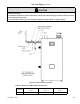
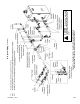
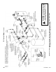
1. Relief Valve (Required) – The relief valve is shipped loose and must be installed in the location shown in Figure 9.1.
ASME Section IV currently requires that this relief valve be installed above the heat exchanger as shown. Pipe the
outlet of the relief valve to a location where water or stream will not create a hazard or cause property damage if the
valve opens. The end of the discharge pipe must terminate in unthreaded pipe. If the relief valve discharge is not
piped to a drain, it must terminate at least 6" above the oor. Do not run the discharge piping through an area that is
prone to freezing. The termination of the relief valve must be in an area where it is not likely to become plugged by
debris.
The relief valve supplied with the boiler is set to open at 30 psi. If it is replaced, the replacement must have
a setting less than or equal to the maximum allowable working pressure (MAWP) shown on the ASME data plate
located on front of heat exchanger.
2. Gauge (Required) - Indicates supply water pressure and temperature. This gauge is shipped loose. Install it as shown
in Figure 9.1.
3. Circulator (required) – A boiler loop circulator is required to maintain ow through boiler. Usually at least
one additional circulator (not supplied) will be required for the system to work properly. See next section for
more information.
4. Expansion Tank (required) – If this boiler is replacing an existing boiler with no other changes in the system,
the old expansion tank can generally be reused. If the expansion tank must be replaced, consult the expansion tank
manufacturer’s literature for proper sizing. If using antifreeze, account for additional expansion of glycol solution
when sizing an expansion tank. In a typical residential heating system, a glycol mixture has an expansion rate about
1.2 times that of water alone, therefore a tank for an anti-freeze system should be at least 1.2 times greater in size.
5. Fill Valve (required) – Either a manual or automatic ll valve may be used, but a manual valve is preferred because
it eliminates unmonitored additions of make-up water to the system. The ideal location for the ll valve is at the
expansion tank. If using antifreeze with automatic ll valve, it is recommended to install a water meter to monitor
makeup water. Antifreeze concentration will decrease as makeup water is added. If using antifreeze, local codes
often require a backow preventer or disconnect from city water.
6. Automatic Air Vent (required) – At least one automatic air vent is required. Manual air vents will usually be required
in other parts of the system to remove air during initial ll.
7. Manual Reset High Limit (required by some codes) (P/N 106056-01) - This control is required by ASME CSD-1 and
some other codes. Install the high limit in the boiler supply piping near the boiler with no intervening valves as shown in
Figure 9.1. Set the manual reset high limit to 200°F. Wire the limit per Figure 10.3 in Section X “Wiring”.
8. Isolation Valves (recommended) - Isolation valves are useful when the boiler must be drained, as they will eliminate
having to drain and rell the entire system.
9. Strainer (recommended) – Install a Y Strainer, or other suitable strainer, to prevent any system debris from entering
the boiler and fouling the water passages. Note that some strainers have a signicant pressure drop, which may
impact the ability of the boiler pump to obtain the required ow. See Paragraph B of this section for additional
information.
10. Drain Valve (required) – Install the drain valve supplied as shown in Figure 9.1.