
Install Instructions


75
107750-01 - 9/17
IX. System Piping (continued)
Boiler
Model
Min. Pipe
Size (in.)
∆T = 35°F ∆T = 30°F ∆T = 25°F ∆T = 20°F
Min.
Flow
(GPM)
Boiler
Head Loss
(ft)
Flow
(GPM)
Boiler
Head Loss
(ft)
Flow
(GPM)
Boiler
Head Loss
(ft)
Max.
Flow
(GPM)
Boiler
Head Loss
(ft)
ASPN-320 1 1/2 17.0 0.5 19.8 0.6 23.8 1.0 29.8 1.6
ASPN-399 1 1/2 21.2 0.8 24.7 1.1 29.7 1.6 37.1 2.5
C. Near Boiler Piping Design
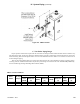
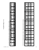
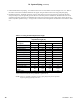
Proper operation of this boiler requires that the water ow rate through it remain within the limits shown in Table 9.3 any
time the boiler is ring. At ow rates below the minimum shown, the boiler’s temperature rise limit function may prevent the
boiler from ring. Flow rates through the boiler in excess of the maximum shown in Table 9.3 can result in excessive noise or
erosion damage to piping.
There are two basic methods that can be used to pipe this boiler into the system. Method #1 (primary-secondary piping)
is always preferred. Additional information on hydronic system design can be found in the I=B=R Guide RHH published by
the Air-Conditioning, Heating and Refrigeration Institute (AHRI).
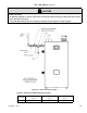
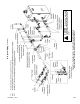
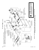
Figure 9.2: LWCO Location
Table 9.3: Flow Limitations