
Install Instructions


76
107750-01 - 9/17
IX. System Piping (continued)
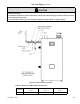
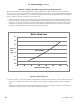
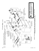
Figure 9.4: Boiler Head Loss
Method 1: Primary/Secondary Piping (Strongly Recommended)
This method can be used in heat-only applications as shown in Figure 9.7a or with an indirect water heater as shown in
Figure 9.7b, 9.7c. In this system, the ow rate through the boiler (“secondary loop”) is completely independent of the ow
rate through the system (“primary loop”). Use the following guidelines to ensure that the boiler will have the required ow
shown in Table 9.3 regardless of the ow in the heating system.
1. System Loop Piping - Size the system circulator and piping to obtain the design ow rate through the heating system
as you would on any other heating system. All piping between the expansion tank and secondary connection tees must
be at least 1". In order to keep the ow rates in the system and boiler loops independent of each other, provide at least
8 diameters of straight pipe upstream of the rst tee and 4 diameters downstream of the second tee. Keep the distance
between the expansion tank and the rst secondary tee as short as practical.
2. Boiler Loop Piping – Size boiler circulator to maintain ow requirements listed in Table 9.3. Boiler head loss is provided
in Figure 9.4. Recommended circulators for 60 equivalent feet of boiler loop piping are listed in Table 9.5a and Table
9.5b.
NOTICE: Use of antifreeze increases boiler and system head loss and may require larger circulators. Consult antifreeze
manufacturer for proper antifreeze concentration and head loss calculation.
0.0
0.5
1.0
1.5
2.0
2.5
3.0
3.5
10 15 20 25 30 35 40 45
Head
Loss
(ft.)
Water Flow Rate (gpm)
Boiler Head Loss
ASPN-320/399