
Install Instructions


78
107750-01 - 9/17
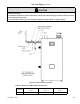
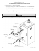
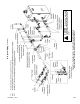
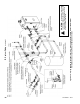
3. Indirect Water Heater Loop Piping – If an indirect water heater is used, install it as shown in Figure 9.7b, 9.7c. Refer to
the indirect water heater installation manual for the proper sizing the indirect water heater loop pump and piping.
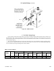
4. Hydraulic Separators – Hydraulic separators serve the same purpose as the closely spaced tees connecting the boiler
and system loops. They also generally provide effective connection points for automatic air elimination devices and an
expansion tank. These separators are available from several sources and may be used in place of the closely spaced tees.
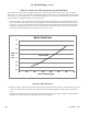
Select a hydraulic separator having 1" or larger boiler connections that is designed for the boiler ow rates shown in Table
9.3.
IX. System Piping (continued)
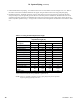
Table 9.6: Fitting and Valve Equivalent Length
Copper Fitting and Sweat Valve
Equivalent Length (Ft)
Fitting or Valve
Description
Copper Pipe or Valve Size
1 1¼ 1½ 2
90° Elbow 2.5 3.0 4.0 5.5
45° Elbow 1.0 1.2 1.5 2.0
Tee (through ow) 0.5 0.6 0.8 1.0
Tee (Branch ow) 4.5 5.5 7.0 9.0
Diverter Tee (typical) 23.5 25.0 23.0 23.0
Gate Valve 0.3 0.4 0.5 0.7
Globe Valve 25.0 36.0 46.0 56.0
Angle Valve 5.3 7.8 9.4 12.5
Ball Valve (standard port) 4.3 7.0 6.6 14.0
Ball Valve (full port) 1.9 1.4 2.2 1.3
Y-Strainer* 7.0
Swing Check Valve 4.5 5.5 6.5 9.0
Flow-Check Valve
(typical)
54.0 74.0 57.0 177.0
Buttery Valve 2.7 2.0 2.7 4.5
* Based on Cv of 20. Pressure drop through strainers varies widely. 7 ft. equivalent+ length
may be assumed for strainers having a published Cv greater than 10.
NOTE: Table 9.3 is provided as reference to assist in piping design and species equivalent
length of typical piping ttings and valves.