
Install Instructions


85
107750-01 - 9/17
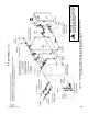
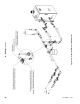
Figure 10.1: Location of High and Low Voltage Printed Circuit Boards (PCB)
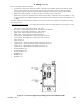
The use of the pump outputs are as follows:
a. System Pump - Pumps water through the radiation. This pump is hydraulically separated from the boiler pump,
either by closely spaced tees, or by a hydraulic separator. The system pump is always on when the system is
responding to a call for CH. Depending on the DHW conguration, it may also be on during a call for DHW.
b. DHW Pump (“IWH Circulator”) - Pumps water directly through the indirect water heater.
c. Boiler Pump - Pumps water through the boiler. Boiler pump is always on when the system is responding to a call
for CH. Depending on the DHW conguration, boiler pump may be turned off when system is responding to a call
for DHW.
Maximum combined current draw for all circulators is 6.3 FLA. See Section XII “Operation” for information on setting
up the pump operation.
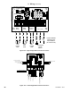
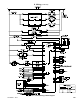
2. Low Voltage Field Connections – Low voltage eld connections on the low voltage PCB are shown in Figure 10.3 and
are listed from top to bottom:
• Heat T’Stat - 24VAC heating thermostat (R - 24V “Hot”)
• Heat T’Stat - 24VAC heating thermostat (W - Energized or Call for Heat)
• Heat T’Stat - 24VAC heating thermostat (C - 24V Common)
• DHW T’Stat - 24VAC domestic hot water thermostat (1)
• DHW T’Stat - 24VAC domestic hot water thermostat (2)
• External Limit - Field supplied low voltage safety limit contacts (1)
• External Limit - Field supplied low voltage safety limit contacts (2)
• Alarm Contact (1)
• Alarm Contact (2)
• Outdoor Sensor - Tasseron TSA00AA Outdoor Temperature Sensor (1)
• Outdoor Sensor - Tasseron TSA00AA Outdoor Temperature Sensor (2)
• Header Sensor - Optional Honeywell 32003971-003 Sensor (1)
• Header Sensor - Optional Honeywell 32003971-003 Sensor (2)
• EnviraCOM Device (D)
• EnviraCOM Device (R)
• EnviraCOM Device (C)
• MODBUS - (A)
• MODBUS - (B)
• MODBUS - (-V)
X. Wiring (continued)