
Install Instructions


87
107750-01 - 9/17
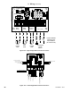
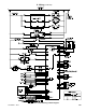
With the exception of the alarm contacts, external power must not be applied to any of the low voltage terminals - doing so
may damage the boiler control. Also note the following:
a. External Limit - The external limit terminals are intended for use with a eld supplied safety device, such as a manual
reset high limit. When an external limit is used, the jumper between these two terminals must be removed. Failure to
remove this jumper will render the external safety devices ineffective.
b. Alarm Contacts - These contacts close when the boiler enters a “hard” lockout (lockout requiring manual reset). They
may be used as an input to a building alarm system. Contact rating is 24VAC, 0.63FLA. Do not use for line voltage
applications.
c. EnviraCOM - Used to connect EnviraCOM thermostat or other EnviraCOM device listed by the boiler manufacturer for
use with this boiler. A Honeywell EnviraCOM connection is also located as labeled on the boiler control itself.
d. Outdoor Sensor - Use only the Tasseron TSA00AA (10 KOhms) outdoor sensor supplied with the boiler. When this
sensor is connected and enabled, the boiler will adjust the target supply water temperature downwards as the outdoor
air temperature increases. This sensor should be located on the outside of the structure in an area where it will sense
the average air temperature around the house. Avoid placing this sensor in areas where it may be covered with ice or
snow. In general, locations where the sensor will pick up direct radiation from the sun should also be avoided. Avoid
placing the sensor near potential sources of electrical noise such as transformers, power lines, and uorescent lighting.
Wire the sensor to the boiler using 22 gauge or larger wire. As with the sensor itself, the sensor wiring should be routed
away from sources of electrical noise. Where it is impossible to avoid such noise sources, wire the sensor using a 2
conductor, UL Type CM, AWM Style 2092 shielded cable. Connect one end of the shielding on this cable to ground.
See Section XII “Operation” for information on enabling the outdoor reset sensor.
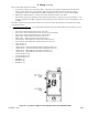
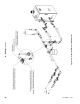
e. Header Sensor - When this sensor is installed and enabled, the boiler will attempt to maintain the target water
temperature in the header rather than in the supply. Where the system ow rate varies widely, the use of a header
sensor allows the temperature of the water being sent to the radiation to be more accurately controlled. Use sensor
P/N 103104-01 (Honeywell 32003971-003) with 1/2" NPT immersion well, P/N 80160456. Installation of this sensor
in a well, as opposed to on the surface of the header, is highly recommended. Alternatively use 1/2" NPT direct
immersion sensor, P/N 101935-01. Locate this sensor immediately downstream of the second primary-secondary Tee
(Figure 10.4). The sensor wiring should be routed away from sources of electrical noise. Where it is impossible to
avoid such noise sources, wire the sensor using a 2 conductor, UL Type CM, AWM Style 2092, 300Volt 60°C shielded
cable. Connect one end of the shielding on this cable to ground. See Section XII “Operation” for information on enabling
the header sensor.
f. MODBUS - Boiler-To-Boiler communication network is used for multiple boiler (“Lead-Lag”) installations. See the
multiple boiler installation supplement for additional information.
X. Wiring (continued)
CAUTION
When making low voltage connections, make sure that no external power source is present in the
thermostat or limit circuits. If such a power source is present, it could destroy the boiler’s control.
One example of an external power source that could be inadvertently connected to the low voltage
connections is a transformer in the old thermostat wiring.
Do not attempt to use EnviraCOM connections for any purpose not explicitly permitted by the boiler
manufacturer. Attempting to do so may result in unreliable operation and/or damage to controls.