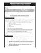
IN S TAL L AT ION , OP E R AT IN G AN D S E R V IC E IN S T R U C T ION S F OR " F D " F O R C E D D R AF T S T E E L BO I L E R BU R N E R U N I T S FOR OIL, GAS OR COMBINATION OIL-GAS FIRING F o r s e r vi c e o r r e p a i r s to b o i le r, c a ll yo ur he a ti ng c o ntr a c to r. W he n s e e k i ng i nfo r m a ti o n o n b o i le r, p r o vi d e B o i le r M o d e l Num b e r a nd S e r i a l Num b e r a s s ho wn o n Ra ti ng L a b e l.
The following terms are used throughout this manual to bring attention to the presence of hazards of various risk levels, or to important information concerning product life. C AU T I O N WAR N IN G In d ic a t e s p r e s e n c e o f a h a z a r d w h ic h w ill o r c a n c a u s e m in o r p e r s o n a l in ju r y o r p r o p e r t y d a m a g e if ig n o r e d .
INTRODUCTION TO "FD" SERIES STEEL BOILER BURNER UNITS N OT IC E Due to an excellent combination of boiler and burner, the "FD" Series boiler-burner units are capable of developing the optimum in combustion and thermal efficiencies. The burner provides 12½% CO2 for a combustion efficiency in excess of 83% on #2 fuel oil. Forced draft operation is accomplished by means of a 3450 RPM motor and blower wheel on the burner and a factory sealed combustion chamber.
FURNACE FLOOR BLANKETS 5. On a flat surface, place the larger diameter 1" thick Bottom Blanket. The furnace floor and the furnace wall below the mud ring are not water backed. These surfaces must be insulated from the intense heat in the furnace. The FD Series boiler now employs precut, refractory ceramic fiber (RCF) blankets to provide this insulation. They are light weight, easy to handle and do not crack like the poured refractory used heretofore. 6.
Im p o r t a n t P r o d u c t S a fe t y In fo r m a t io n R e fr a c t o r y C e r a m ic F ib e r P r o d u c t Warning: This product contains refractory ceramic fibers (RCF). RCF has been classified as a possible human carcinogen. After this product is fired, RCF may, when exposed to extremely high temperature (>1800F), change into a known human carcinogen. When disturbed as a result of servicing or repair, RCF becomes airborne and, if inhaled, may be hazardous to your health.
CLEANING INSTRUCTIONS 9
FD BURNER SPECIFICATIONS B OIL E R MOD E L NUMB E R: F D O, F D G, F D GO 7 9 10 12 #2 Oil C F 500 C F 500 C F 500 CF800 (A) Power Flame "CR" Gas/#2 Oil CR-1-GO-10 CR-1-GO-10 CR-1-GO-10 CR-1-GO-10 Power Flame "JR" Gas JR-15A-10 JR-15A-10 JR-15A-10 JR-15A-10 Beckett "CF" 1/3, 120/60/1 1/3, 120/60/1 1/3, 120/60/1 1/3, 120/60/1 Power Flame "CR" 1/3, 120/60/1 1/3, 120/60/1 1/3, 120/60/1 1/2, 120/60/1 Power Flame "JR" 1/4, 120/60/1 1/4, 120/60/1 1/4, 120/60/1 1/4, 120/60/1 Be
FD BURNER SPECIFICATIONS 14 15 19 24 30 38 45 CF800 (A) CF800 (A) CF800 (A) CF1400 (A) CF1400 (A) CF2300 (A) CF2300 (A) CR-1-GO-10 CR-1-GO-10 CR-1-GO-12 CR-1-GO-12 CR-1-GO-12 CR-2-GO-15 CR-2-GO-15 JR-15A-10 JR-30A-10 JR-30A-10 JR-30A-10 JR-50A-15 JR-50A-15 JR-50A-15 1/3, 120/60/1 1/3, 120/60/1 1/3, 120/60/1 1/2, 120/60/1 1/2, 120/60/1 3/4, 120/60/1 3/4, 120/60/1 1/2, 120/60/1 1/2, 120/60/1 1/2, 120/60/1 1/2, 120/60/1 3/4, 230/60/1 3/4, 230/60/1 3/4, 230/60/1 1/4, 12
BECKETT CF500/800 OIL BURNER B urne r A i r* A i r* No zzle D a ta B o i le r Mo unti ng B urne r F i ri ng Ra te F a n S i ze A i r Tub e S hutte r B a nd He a d * Mo d e l P la te Re q . Mo d e l (G.P.H.) (In.) C o mb i na ti o n S e tti ng S e tti ng S e tti ng G.P.H. A ng le Typ e M fg . P ump P re s s ure (P S I) FD 7 6023401 C F500 2 .3 2 .4 x 5 .6 C F60K K 0 3 .5 1 1 .7 5 45º P Ha g o 150 FD 9 6023401 C F500 2 .7 5 2 .4 x 5 .6 C F60K K 0 4 2 2 .
BECKETT CF1400 OIL BURNER BECKETT CF2300 OIL BURNER No zzle D a ta B urne r L o w* Hi g h* B o i le r Mo unti ng B urne r F i ri ng Ra te F a n S i ze A i r Tub e F i re F i re He a d * Mo d e l P la te Re q . Mo d e l (G.P.H.) (In.) C o mb i na ti o n A i r A i r S e tti ng G.P.H. A ng le Typ e P ump P re s s ure M fg . FD 24 6023443 C F1400 7 .5 3 .1 x 5 .6 C F60K D 3 .0 5 .5 3 .0 4 .5 45º P Ha g o 150 300 FD 30 6023443 C F1400 9 .5 3 .1 x 5 .6 C F60K E 3 .0 7 .5 1 .5 5 .
TANKLESS HEATER PERFORMANCE Check and if necessary torque coil plate nuts to 25 ft.lb. max (Do Not Over Torque) before filling system and again after the boiler has been up to operating temperature for several hours. Tankless heater ratings in the FD boiler are based on continuous draw, temperature rise of 100°F (40-140°F) and boiler water temperature of 200°F. Some of the items effecting the coil performance are as follows: 3.
H E AT E R R AT IN GS - " F D " F OR C E D D R AF T B OIL E R S B o ile r M o d e l C o il N o . C o il P a s s * Ga llo n s P e r H o u r B a s e d On 1 0 0 °F R is e P r e s s u r e D r o p (P.S .I.) At F lo w R a t e F o r 1 0 0 °F R is e FD 7 A -3 4 A 2 300 1 0 .5 FD 9 A -3 4 A 2 360 1 5 .3 FD 10 A -3 4 B 2 420 2 0 .8 FD 12 3 -8 2 480 1 9 .2 FD 14 3 -9 2 540 2 7 .0 FD 15 3 -1 0 3 600 11 .0 FD 19 3 -1 2 3 720 1 8 .8 FD 24 3 -1 6 5 960 8 .
INDIRECT WATER HEATER OPERATION build up to the point of total obstruction. It is recommended that the local water supply be checked and treated as may be recommended. The Forced Draft Boiler with a tankless heater coil for domestic hot water supply is an efficient and easily maintained system to provide large volumes of domestic hot water. An indirect tankless water heater is one in which domestic water is heated as it passes through a copper coil immersed in hot boiler water.
VENT SIZING - AREA MUST BE THE SAME AS OR GREATER THAN THE BOILER BREECHING (Smoke outlet). A BAROMETRIC DAMPER MAY BE REQUIRED ON INSTALLATIONS WITH A HIGH DRAFT CONDITION. FAULTY BOILER BURNER OPERATION 1. IF IMPROPER VENT IS SUSPECTED, REMOVE PIPE AT BREECHING AND OPERATE BOILER. THIS WILL DETERMINE IF EXCESSIVE DOWN DRAFT, BLOCKED OR RESTRICTED FLUE, ETC. IS CAUSING PROBLEM. 2. IF USING TYPE SHOWN IN A. ABOVE, BE SURE CAP IS RAISED SUFFICIENTLY ABOVE MAIN PIPE TO ALLOW FLUE GASES TO VENT UNIMPEDED. 3.
EXPANSION OR AIR CUSHION TANK a pocket or cushion of air is trapped within the tank. This air cushion provides the additional space required to accommodate the increased volume of water caused by thermal expansion. The use of an expansion tank permits operation through all ranges of boiler water temperature, including temperatures above 212ºF without opening the safety-relief valve.
OXYGEN CORROSION Oxygen contamination of the boiler water will cause corrosion of the iron and steel boiler components, which can lead to failure. As such, any system must be designed to prevent oxygen absorption in the first place or prevent it from reaching the boiler. Problems caused by oxygen contamination of boiler water are not covered by Burnham’s standard warranty. In order to insure long product life, oxygen sources should be eliminated.
All FD Series Repair Parts may be obtained through your local Burnham Wholesale distributor. Should you require assistance in locating a Burnham Distributor in your area, or have questions regarding the availability of Burnham products or repair parts, please contact Burnham Customer Service at (717) 481-8400 or Fax (717) 481-8408. When ordering repair parts, refer to: (1) the part description on this page or page 4, (2) the Boiler Model Number and (3) the Boiler Serial Number.
Limited Warranty FD SERIES™ Limited Warranty – Except as provided below with respect to products or parts not manufactured by Burnham Commercial™, Burnham Commercial warrants to the original owner at the original installation site that products manufactured by Burnham Commercial, America’s Boiler Company comply, at the time of manufacture, with recognized Hydronics industry regulatory agency standards and requirements then in effect and will be free from defects in materials and workmanship for a period of