INSTALLATION INSTRUCTIONS FOR K2™ CONDENSING HIGH EFFICIENCY DIRECT VENT GAS - FIRED HOT WATER BOILER 9700609 As an ENERGY STAR® Partner, U.S. Boiler Company has determined that the K2™ Series meets the ENERGY STAR® guidelines for energy efficiency established by the United States Environmental Protection Agency (EPA). Warning: Improper installation, adjustment, alteration, service or maintenance can cause property damage, injury, or loss of life.
IMPORTANT INFORMATION - READ CAREFULLY NOTE: The equipment shall be installed in accordance with those installation regulations enforced in the area where the installation is to be made. These regulations shall be carefully followed in all cases. Authorities having jurisdiction shall be consulted before installations are made. All wiring on boilers installed in the USA shall be made in accordance with the National Electrical Code and/or local regulations.
WARNING Asphyxiation Hazard. This boiler requires regular maintenance and service to operate safely. Follow the instructions contained in this manual. Improper installation, adjustment, alteration, service or maintenance can cause property damage, personal injury or loss of life. Read and understand the entire manual before attempting installation, start-up operation, or service. Installation and service must be performed only by an experienced, skilled, and knowledgeable installer or service agency.
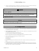
Special Installation Requirements for Massachusetts A. For all sidewall horizontally vented gas fueled equipment installed in every dwelling, building or structure used in whole or in part for residential purposes and where the sidewall exhaust vent termination is less than seven (7) ft. above grade, the following requirements shall be satisfied: 1.
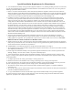
WARNINGS FOR THE HOMEOWNER FOLLOW ALL INSTRUCTIONS and warnings printed in this manual and posted on the boiler. unless alarms or other safeguards are in place to prevent such damage MAINTAIN THE BOILER. To keep your boiler safe and efficient, have a service technician maintain this boiler as specified in Service and Maintenance manual. DO NOT BLOCK AIR FLOW into or around the boiler. Insufficient air may cause the boiler to produce carbon monoxide or start a fire.
Table of Contents I. II. III. IV. V. VI. VII. Product Description Specifications Before Installing Locating The Boiler Mounting The Boiler Air For Ventilation Venting A. Vent System Design B. Design Requirements Unique to Horizontal Twin Pipe Venting Systems C. Design Requirements Unique to Vertical Venting Systems D. Design Requirements Unique to Split Vent Systems E. Assembly of CPVC/PVC Vent Systems F. Assembly of DuraVent PolyPro Vent Systems G. Assembly of Selkirk Polyflue Vent Systems H.
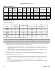
I. Product Description This boiler is a stainless steel gas fired condensing boiler designed for use in forced hot water heating systems requiring supply water temperatures of 180°F or less. It is designed for installation on a wall. This boiler may be vented vertically or horizontally with combustion air supplied from outdoors. It is not designed for use in gravity hot water systems or systems containing significant amounts of dissolved oxygen. II. Specifications SEE TABLE 2.
II. Specifications (continued) Table 2.2: Specifications Model* Maximum Minimum Input Input (MBH) (MBH) D.O.E. Heating Capacity (MBH) Approx. AHRI Net Water Supply & Return Dim. Gas Connection Net Rating * Volume Connection “A” Size (NPT) Weight (MBH) (gal.) Size (NPT) (lb.) K2-080 80 16 74 64 0.36 17” 1” 1/2” 100 K2-100 100 20 92 80 0.44 17” 1” 1/2” 102 K2-120 120 24 111 97 0.53 17” 1” 1/2” 105 K2-150 150 30 141 123 0.
III. Before Installing (continued) 4. All boilers are shipped from the factory configured for use with natural gas. They may be converted for use with LP gas (“propane”) using a combustion analyzer in accordance with the instructions in Appendix A. DANGER • Do not attempt to operate this boiler on LP gas without converting it in accordance with the instructions shown in Appendix A. • Do not attempt to convert this boiler to LP gas without the use of a combustion analyzer.
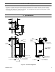
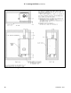
IV. Locating the Boiler (continued) Figure 4.
V. Mounting The Boiler A. Wall Mounting CAUTION This boiler weighs as much as 119 pounds: • • Two people are required to safely lift this boiler onto the wall mounting hook. Make sure that wall mounting hook is anchored to a structure capable of supporting the weight of the boiler and attached piping when filled with water. Jurisdictions in areas subject to earthquakes may have special requirements for supporting this boiler. These local requirements take precedence over the requirements shown below. 1.
V. Mounting The Boiler (continued) Figure 5.
V. Mounting The Boiler (continued) Figure 5.
VI . Air for Ventilation WARNING Outdoor combustion air must be piped to the air intake. Never pipe combustion air from areas containing contaminates such as swimming pools and laundry room exhaust vents. Contaminated combustion air will damage the boiler and may cause property damage, personal injury or loss of life. Air for combustion must always be obtained directly from outdoors. See Section VII for intake piping.
VII. Venting WARNING Asphyxiation Hazard. Failure to vent this boiler in accordance with these instructions could cause products of combustion to enter the building resulting in severe property damage, personal injury or death. Do not interchange vent systems or materials unless otherwise specified. The use of thermal insulation covering vent pipe and fittings is prohibited. Do not use a barometric damper, draft hood or vent damper with this boiler.
VII. Venting A. Vent System Design (continued) Figure 7.0a: Horizontal Twin Pipe Figure 7.0b: Vertical Twin Pipe Figure 7.
VII. Venting A. Vent System Design (continued) • DuraVent PolyPro - ULC S636 listed Polypropylene special gas vent system. Use of flex piping is not permitted. • Selkirk Polyflue - ULC S636 listed Polypropylene special gas vent system. • Centrotherm InnoFlue SW - ULC S636 listed Polypropylene special gas vent system. Use of flex piping is not permitted. Use PVC and/or CPVC for the air intake system. PVC may be used for all air intake piping between the intake terminal and the boiler.
VII. Venting A. Vent System Design (continued) 4. Minimum Vent and Air Intake Lengths - Observe the minimum vent lengths shown in Tables 7.1, 7.13 and 7.21. 5. Clearances to Combustibles - Maintain the following clearances from the vent system to combustible construction: • Vent - 1/4” (also observe clearances through both combustible and non-combustible walls - see 9 below) • Air Intake - 0” • Concentric Portion of Concentric Terminals - 0” 6.
VII. Venting A. Vent System Design (continued) 7. Supporting Pipe - Vertical and horizontal sections of pipe must be properly supported. Maximum support spacing is as follows: • • • • Support CPVC/PVC horizontally and vertically every 4 feet. Support DuraVent PolyPro horizontally near the female end of each straight section of pipe and vertically every 10 feet. Support Centrotherm InnoFlue horizontally every 39 inches with additional supports at elbows and vertically every 78”.
VII. Venting A. Vent System Design (continued) Figure 7.3a Figure 7.3b Figure 7.3c Figure 7.3: Expansion Loops for CPVC/PVC Pipe Figure 7.
VII. Venting B. Design Requirements Unique to Horizontal Twin Pipe Venting Systems (continued) B. Design Requirements Unique to Horizontal Twin Pipe Venting Systems Table 7.5 summarizes all horizontal twin pipe vent options. Illustrations of horizontal twin pipe vent systems are shown in Figures 7.6 – 7.10. In addition to the requirements in Part VII-A, observe the following design requirements: 1.
VII. Venting B. Design Requirements Unique to Horizontal Twin Pipe Venting Systems (continued) Table 7.5: Summary of Horizontal Twin Pipe Venting Options Vent Option 7.6, 7.7, 7.8 1 7.6, 7.7, 7.8 3 4 5 6 7 8 7.9, 7.10 7.9, 7.10 7.9 7.9 7.9 7.
2. VII. Venting B. Design Requirements Unique to Horizontal Twin Pipe Venting Systems (continued) Horizontal Vent and Air Intake Terminal Location - Observe the following limitations on the vent terminal location (also see Figure 7.11). When locating a concentric terminal, observe the limitations outlined below for “vent terminals”. • Vent terminal must be at least 1 foot from any door, window, or gravity inlet into the building.
VII. Venting B. Design Requirements Unique to Horizontal Twin Pipe Venting Systems (continued) Figure 7.7: Horizontal CPVC/PVC Venting with Low Profile Terminal, (Vent Options #1 & 2, Terminal Options B & C) Figure 7.
VII. Venting B. Design Requirements Unique to Horizontal Twin Pipe Venting Systems (continued) Figure 7.9: Duravent PolyPro, Selkirk, Polyflue or Centrotherm InnoFlue Horizontal Venting (Vent Option #3 - 8, Terminal Option A) Figure 7.
Figure 7.11: Location of Vent Terminal Relative to Windows, Doors, Grades, Overhangs, Meters and Forced Air Inlets - Two-Pipe System Vent Terminal (Shown) Two-Pipe System Air Intake Terminal (Not Shown) Note: Air intake termination not shown, refer to Venting Section in K2 Installation Instructions supplied with the boiler. VII. Venting B.
VII. Venting C. Design Requirements Unique to Vertical Venting Systems (continued) Figure 7.12: Snorkel Terminal Configuration (CPVC/PVC Vent Systems Only) C. Design Requirements Unique to Vertical Venting Systems Table 7.13a summarizes all vertical twin pipe vent options. Table 7.13.b summarizes vent options in which an abandoned B-vent chimney is used both as a chase for the vent pipe and as a conduit for combustion air.
VII. Venting C. Design Requirements Unique to Vertical Venting Systems (continued) Table 7.13a: Summary of Vertical Twin Pipe Venting Options Option 10 11 12 13 14 15 16 17 7.15, 717 7.15, 7.17 7.17, 7.18 7.17, 7.18 7.17 7.17 7.17 7.
VII. Venting C. Design Requirements Unique to Vertical Venting Systems (continued) Table 7.13b: Summary of Vertical “B-Vent Air Chase” Vent Options (B-Vent Chase MUST Be Sealed) Option 18 19 20 21 7.19 7.19 7.20 7.
VII. Venting C. Design Requirements Unique to Vertical Venting Systems (continued) Terminal Option J: DiversiTech Concentric Terminal (Acceptable for Vent Options 10 & 11) - This terminal is shown in Figure 7.16 and may be used with CPVC/PVC vent systems. See Part VII-E of this manual and the DiversiTech instructions provided with the terminal, for installation details. Terminal Option K: DuraVent PolyPro Concentric Terminal (Acceptable for Vent Options 12, 13) - This terminal is shown in Figure 7.
VII. Venting C. Design Requirements Unique to Vertical Venting Systems (continued) Table 7.14: Equivalent Length of Flex Pipe Equivalent Length (ft) Flex Vent (1 ft): 2” DuraVent PolyPro Flex 2.0 ft 2” Centrotherm InnoFlue Flex 2.0 ft 2” Selkirk Polyflue 2.0 ft 3” DuraVent PolyPro Flex 2.0 ft 3” Centrotherm InnoFlue Flex 2.3 ft 3” Selkirk Polyflue 2.3 ft 2” Flex Vent in 5” (or larger) B-Vent 1.0 ft 3” Flex Vent in 6” (or larger) B-Vent 1.
VII. Venting C. Design Requirements Unique to Vertical Venting Systems (continued) Figure 7.15: Vertical CPVC/PVC Venting (Vent Options 10 & 11, Terminal Option H) Figure 7.
VII. Venting C. Design Requirements Unique to Vertical Venting Systems (continued) Figure 7.17: Duravent PolyPro, Selkirk Polyflue or Centrotherm InnoFlue Vertical Single Wall PP Venting (Vent Options #12-17, Terminal Option H) Figure 7.
VII. Venting C. Design Requirements Unique to Vertical Venting Systems (continued) Figure 7.19: Duravent PolyPro B-Vent Air Chase System (Vent Options #18 & 19) 34 Figure 7.
VII. Venting D. Design Requirements Unique to Split Vent Systems (continued) D. Design Requirements Unique to Split Vent Systems Table 7.21 summarizes all split vent options. Illustrations of split vent systems are shown in Figures 7.22, 7.23, and 7.24. In addition to the requirements in Part VII-A, observe the following design requirements: 1.
VII. Venting D. Design Requirements Unique to Split Vent Systems (continued) Example: A 100MBH model is to be installed as using Vent Option 34 in a masonry chimney as shown in Figure 7.23.
THIS PAGE LEFT BLANK INTENTIONALLY 105294-05 - 5/15 37
VII. Venting D. Design Requirements Unique to Split Vent Systems (continued) Table 7.21: Summary of Split Vent System Options Option # 25 26 27 28 29 30 7.22 7.22 7.22 7.22 7.22 7.
VII. Venting D. Design Requirements Unique to Split Vent Systems (continued) Table 7.21: Summary of Split Vent System Options (cont.) 31 32 33 34 35 36 37 38 7.22 7.22 7.23, 7.24 7.23, 7.24 7.23, 7.24 7.23, 7.24 7.23, 7.24 7.23, 7.
VII. Venting D. Design Requirements Unique to Split Vent Systems (continued) Figure 7.22: Split Rigid Vent System (Vent Options 25-32) Figure 7.
VII. Venting D. Design Requirements Unique to Split Vent Systems (continued) Figure 7.
VII. Venting D. Design Requirements Unique to Split Vent Systems (continued) Venting of Other Appliances (Or Fireplace) into Chase or Adjacent Flues Prohibited! Figure 7.
VII. Venting E. Assembly of CPVC/PVC Vent Systems (continued) E. Assembly of CPVC/PVC Vent Systems WARNING Asphyxiation Hazard. Failure to follow these instructions could cause products of combustion to enter the building, resulting in severe property damage, personal injury or death. Use all CPVC vent components (supplied with the boiler) for near-boiler vent piping before transitioning to Schedule 40 PVC pipe (ASTM 2665) components for remainder of vent system.
VII. Venting E. Assembly of CPVC/PVC Vent Systems (continued) Figure 7.27: Vent Connections and Flue Gas Sample Cap Location g. Assemble the rest of the vent system, being sure to pitch horizontal sections back towards the boiler 1/4”/ft. Support the vent at intervals not exceeding 4ft. h. Maintain the clearances from the vent pipe outlined in Part VII-A of this manual.
VII. Venting E. Assembly of CPVC/PVC Vent Systems (continued) Figure 7.28: Installation of Standard Horizontal Terminals Figure 7.
5. 6. 7. 8. VII. Venting E. Assembly of CPVC/PVC Vent Systems (continued) Installation of Vertical Fitting Terminals (Terminal Option H): a. See Figure 7.29 for the proper orientation of twin pipe vertical terminals. b. The coupling is used to secure the rodent screen to the end of the vent pipe. c. A 180° bend (or two 90° elbows) are installed on the top of the air intake pipe. If two 90° elbows are used, the rodent screen provided can be installed between them (Figure 7.29).
VII. Venting E. Assembly of CPVC/PVC Vent Systems (continued) Figure 7.30: Installation of IPEX Low Profile Terminal Through Sidewall Figure 7.
VII. Venting E. Assembly of CPVC/PVC Vent Systems (continued) Figure 7.32: Cutting IPEX and DiversiTech Concentric Vent Terminals Figure 7.
VII. Venting E. Assembly of CPVC/PVC Vent Systems (continued) Figure 7.34: Installation of IPEX and DiversiTech Concentric Terminal Through Roof b. For vertical installations, cut a hole in the roof large enough to clear the concentric terminal at the location of the terminal (see Part VII-C of this manual for permitted terminal locations). c. If desired, the terminal can be shortened. See Figure 7.32 for specific information on making the terminal kit shorter based on the kit size being used.
VII. Venting F. Assembly of DuraVent PolyPro Vent Systems (continued) F. Assembly of DuraVent PolyPro Vent Systems 1. This boiler has been approved for use with the DuraVent PolyPro single wall Polypropylene vent system to be provided by the installer. WARNING Asphyxiation Hazard. Follow these instructions and the installation instructions included by the original Polypropylene venting component manufacturers, M&G/DuraVent.
VII. Venting F. Assembly of DuraVent PolyPro Vent Systems (continued) 3. Installation of Air Intake System - Start assembly of the PVC air intake system at the boiler. Assembly of the air intake system is done in the same manner as the vent system except as follows: a. Drill a 7/32” clearance hole into the front side of the air intake adapter.
VII. Venting F. Assembly of DuraVent PolyPro Vent Systems (continued) Figure 7.36: Installation of Duravent PolyPro UV Resistant Single Wall Horizontal Terminal Figure 7.
VII. Venting F. Assembly of DuraVent PolyPro Vent Systems (continued) 6. Installation of DuraVent PolyPro Horizontal Concentric Vent Terminal (Terminal Option D) Install PolyPro Horizontal Concentric Termination Kit #2PPS-HK or #3PPS-HK (Figure 7.39) as follows: a. At the planned location cut a 4-1/8” round hole for the 2” terminal or a 5-1/8” round hole for the 3” terminal in the exterior wall. (See Part VII-A of this manual for permitted terminal locations). b. If desired, the terminal can be shortened.
VII. Venting F. Assembly of DuraVent PolyPro Vent Systems (continued) Figure 7.
VII. Venting F. Assy of DuraVent PolyPro & G. Selkirk Polyflue Vent Systems (continued) 8. Installations using PolyPro-flex (Vent Options 18,19,33,34): WARNING Asphyxiation Hazard. When using PolyPro flex, observe the following precautions: • PolyPro flex may be damaged by handling at low temperatures. Do not bend, uncoil, or attempt to install if it has been stored at a temperature below 42°F without allowing it to warm to a higher temperature first. • Do not bend PolyPro flex more than 45°.
VII. Venting G. Assembly of Selkirk Polyflue Vent Systems (continued) e. Support each pipe section as described in Polyflue manual at intervals not exceeding the following: Pipe size 2” 3” Horizontal 30in 39in Vertical 16ft 16ft NOTICE Once a vent pipe is inserted into this adaptor, it is IMPOSSIBLE to remove it. Make sure the correct type of pipe is selected, and that it is of the correct length, before inserting it into the vent adaptor. 3.
VII. Venting G. Assembly of Selkirk Polyflue Vent Systems (continued) 6. Installations using flexible Polyflue (Vent Options 35,36): WARNING Asphyxiation Hazard. When using Polyflue flex, observe the following precautions: • Polyflue flex may be damaged by handling at low temperatures. Do not bend, uncoil or attempt to install if it has been stored at a temperature below 42°F without allowing it to warm to a higher temperature first. • Do not bend Polyflue flex more than 45°.
VII. Venting G. Assembly of Selkirk Polyflue Vent Systems (continued) Figure 7.42: Installation of Selkirk Polyflue UV Resistant Single Wall Horizontal Terminal Figure 7.
VII. Venting H. Assembly of Centrotherm InnoFlue Vent Systems H. Assembly of Centrotherm InnoFlue Vent Systems 1. This boiler has been approved for use with the Centrotherm InnoFlue single wall Polypropylene vent system to be provided by the installer. WARNING Asphyxiation Hazard. Follow these instructions and the installation instructions included by the original Polypropylene venting component manufacturers, Centrotherm.
VII. Venting H. Assembly of Centrotherm InnoFlue Vent Systems 3. Installation of Air Intake System - Start assembly of the PVC air intake system at the boiler. Assembly of the air intake system is done in the same manner as the vent system except as follows: a. Drill a 7/32” clearance hole into the front side of the air intake adapter.
VII. Venting H. Assembly of Centrotherm InnoFlue Vent Systems Figure 7.45: Installation of Centrotherm InnoFlue UV Stabilized Single Wall Horizontal Terminal Figure 7.
VII. Venting H. Assembly of Centrotherm InnoFlue Vent Systems 6. Installations using InnoFlue Flex (Vent Options 20,21,37,38): WARNING Asphyxiation Hazard. When using InnoFlue Flex, observe the following precautions: • InnoFlue Flex may be damaged by handling at low temperatures. Do not bend, uncoil or attempt to install if it has been stored at a temperature below 42°F without allowing it to warm to a higher temperature first. • Do not bend InnoFlue Flex more than 45°.
VII. Venting I. Condensate Trap and Drain Line (continued) I. Condensate Trap and Drain Line All condensate which forms in the boiler or vent system passes through the heat exchanger and out of a bottom drain port which is connected to the condensate trap with a hose. This trap allows condensate to drain from the heat exchanger while retaining flue gases in the boiler. This trap is an integral part of the boiler but must be connected to a drain pipe as shown in Figure 7.47.
VII. Venting J. Removing an Existing Boiler From a Common Chimney (continued) J. Removing an Existing Boiler From a Common Chimney This section only applies if this boiler is replacing an existing boiler that is being removed from a common chimney. In some cases, when an existing boiler is removed from a common chimney, the common venting system may be too large for the remaining appliances.
VIII. Gas Piping WARNING Explosion Hazard. Failure to properly pipe gas supply to boiler may result in improper operation or leaks of flammable gas. Gas supply to boiler and system must be absolutely shut off prior to installing or servicing boiler gas piping. Always assure gas piping is absolutely leak free and of the proper size and type for the connected load. Use a thread compound compatible with liquefied petroleum gas.
VIII. Gas Piping (continued) CAUTION Support the weight of the gas line piping independently from the boiler gas connection fitting located on the bottom of the boiler. If an additional regulator is used to reduce boiler inlet pressure below 1/2 psig (3.4 kPa) it must be at least 6 to 10 ft. upstream of the boiler. It is very important that the gas line is properly purged by the gas supplier or utility company. Figure 8.1: Gas Connection to Boiler Table 8.
IX. System Piping A. General System Piping Precautions WARNING Failure to properly pipe boiler may result in improper operation and damage to boiler or structure. Install boiler so that the gas ignition system components are protected from water (dripping, spraying, rain, etc.) during boiler operation and service (circulator replacement, etc.). Oxygen contamination of boiler water will cause corrosion of iron and steel boiler components and can lead to boiler failure.
IX. System Piping (continued) B. Near Boiler Piping Design Proper operation of this boiler requires that the water flow rate through it remain within the limits shown in Table 9.1 any time the boiler is firing. At flow rates below the minimum shown, the boiler’s flow switch and/or temperature rise limit function may prevent the boiler from firing. Flow rates through the boiler in excess of the maximum shown in Table 9.
105294-05 - 5/15 69 Figure 9.2: Piping Method #1 - Near Boiler Piping - Heating Only IX.
105294-05 - 5/15 Figure 9.
105294-05 - 5/15 71 Figure 9.3a: Piping Method #1 - Near Boiler Piping - Heating Plus Indirect Water Heater IX.
IX. System Piping (continued) Figure 9.
IX. System Piping (continued) Example – A 120MBH model is to be connected to a heating system as shown in Figure 9.6. A total of 20 ft of straight pipe will be installed between the boiler and the system loop. Count all fittings in the boiler loop (shaded in Figure 9.6): 3 90° Elbows 2 Turn in Tee (under boiler- primary-secondary tees not counted) 2 Isolation Valves 1 Y Strainer having a Cv of 30. Note: Unions, Secondary Connection Tees, and factory supplied fittings are ignored.
IX. System Piping (continued) Figure 9.
IX. System Piping (continued) Method 2: Direct Connection to Heating System (Generally NOT Recommended) In some relatively rare cases it may be possible to connect this boiler directly to the heating system as is done with conventional boilers (Figure 9.7). If this is done, the flow rate through the boiler will equal the flow rate through the system. The flow rate through the system must therefore always remain within the limits shown in Table 9.1.
IX. System Piping (continued) Note: These curves show the flow that can be achieved through the boiler as a function of the pressure drop through the connected piping. Figure 9.8a: Taco Net Circulator Performance Curve Figure 9.8b: Grundfos Net Circulator Performance Curve Note: Must use Speed HI to achieve the flow requirement shown in Table 9.
IX. System Piping (continued) C. Standard Piping Installation Requirements Observe the following requirements when installing the boiler piping: 1) Relief Valve (Required) – The relief valve is shipped loose and must be installed in the location shown in Figure 9.9, using the side outlet Tee and other fittings provided. ASME Section IV currently requires that this relief valve be installed above the heat exchanger as shown.
IX. System Piping (continued) 10) Drain Valve (required) – Install the drain valve supplied as shown in Figure 9.9. 11) Low Water Cut-off (may be required by local jurisdiction) – Protection of this boiler against low water and/or inadequate flow is provided by the UL353 certified flow switch built into the boiler. This is a water tube boiler and this flow switch is therefore the only effective way to provide such protection.
IX. System Piping (continued) D. Piping for Special Situations 1) Systems containing oxygen - Many hydronic systems contain enough dissolved oxygen to cause severe corrosion damage to a this boiler. Some examples include: • Radiant systems that employ tubing without an oxygen barrier. • Systems with routine additions of fresh water. • Systems which are open to the atmosphere.
X. Wiring DANGER Electrical Shock Hazard. Positively assure all electrical connections are unpowered before attempting installation or service of electrical components or connections of the boiler or building. Lock out all electrical boxes with padlock once power is turned off. WARNING All wiring and grounding must be done in accordance with the authority having jurisdiction or, in the absence of such requirements, with the National Electrical Code /NFPA 70).
X. Wiring (continued) The use of the pump outputs are as follows: a) System Pump - Pumps water through the radiation. This pump is hydraulically separated from the boiler pump, either by closely spaced tees, or by a hydraulic separator. The system pump is always on when the system is responding to a call for CH. Depending on the DHW configuration, it may also be on during a call for DHW. b) DHW Pump (“IWH Circulator”) - Pumps water directly through the indirect water heater.
X. Wiring (continued) Figure 10.2: High Voltage PCB Terminal Connections Figure 10.
X. Wiring (continued) • • • • • • • Outdoor Sensor - Tasseron TSA00AA Outdoor Temperature Sensor (1) Outdoor Sensor - Tasseron TSA00AA Outdoor Temperature Sensor (2) Header Sensor - Optional Honeywell 32003971-003 (103104-01) Sensor (1) Header Sensor - Optional Honeywell 32003971-003 (103104-01) Sensor (2) MODBUS - (A) MODBUS - (B) MODBUS - (-V) With the exception of the alarm contacts, external power must not be applied to any of the low voltage terminals - doing so may damage the boiler control.
X. Wiring (continued) Figure 10.
X. Wiring (continued) 120V Line L N G Boiler Control (R7910B) F1 (6.3A Slow Blow) J4‐2 P3‐11 J4‐4 J4‐5 P3‐7 J4‐6 J4‐7 J4‐3 DHW(N) DHW(L) P3‐4 P3‐10 DHW Pump L1‐1 L1‐2 P3‐1 Grounded to Boiler Frame via PCB Standoff/Mounting Screw Boiler Pump SYS(L) P3‐6 SYS(N) System Pump Combustion Fan (120V Conn.) 1 P3‐9 Ground Screw Bottom Panel 3 2 P3‐2 Internal, non replaceable 2 amp P3‐12 F2 (1.
105294-05 - 5/15 X.
105294-05 - 5/15 87 Figure 10.6: Internal Wiring Connections Diagram X.
X. Wiring (continued) Table 10.7: Internal Wire Connection Markings Cross Reference Table WIRE NO. IN FIG. 10.5 WIRE MARKING WIRE NO. IN FIG 10.
X. Wiring (continued) Figure 10.
X. Wiring (continued) Figure 10.
XI. Start-Up and Checkout WARNING Completely read, understand and follow all instructions in this manual before attempting start-up. NOTICE Safe lighting and other performance criteria were met with the gas train assembly provided on the boiler when the boiler underwent the test specified in Z21.13. Use the following procedure for initial start-up of the boiler: 1) Verify that the venting, water piping, gas piping and electrical system are installed properly.
XI. Start-Up and Checkout (continued) DANGER Asphyxiation Hazard. Failure to properly convert this boiler for use on lp gas can cause unreliable operation at elevated carbon monoxide (CO) levels, resulting in personal injury or death.
XI. Start-Up and Checkout (continued) Figure 11.1: Location of Manual Air Vent 11) Start the boiler using the lighting instructions on page 97. With the boiler powered up, and with no call for heat, the display should look like Figure 11.2a. Once a call for heat is present, it will look like Figure 11.2b. 12) The boiler should attempt to fire approximately 30 seconds after a call for heat appears.
XI. Start-Up and Checkout (continued) Figure 11.2a: Home Screen at Power-Up (No Call for Heat) Figure 11.2b: Home Screen on Heat Demand Figure 11.2c: Home Screen with Active Fault Figure 11.
XI. Start-Up and Checkout (continued) WARNING Asphyxiation Hazard. Each boiler is tested at the factory and adjustments to the air fuel mixture are normally not necessary when operating on natural gas at sea level. Consult the factory before attempting to make any such adjustments. Improper gas valve or mixture adjustments could result in property damage, personal injury or loss of life due to carbon monoxide (CO) poisoning. WARNING Asphyxiation Hazard.
XI. Start-Up and Checkout (continued) 16) Perform a combustion test. Boilers are equipped with a screw cap in the vent adapter. Be sure to replace this cap when combustion testing is complete. Check CO2 (or O2) and CO at both high and low fire. The boiler may be temporarily locked into high or low fire as follows: a) Fire the boiler through any call for heat. b) From the Home Screen, press “ADJUST” to enter the adjust menu. c) Press “ADJUST”. d) Press “LOGIN”. e) Press “000”. f) Enter the password “086”.
XI.
Appendix A: Instructions for Conversion of this Boiler for use with LP Gas DANGER These instructions include a procedure for adjusting the air-fuel mixture on this boiler. This procedure requires a combustion analyzer to measure the CO2 (or Oxygen) and Carbon Monoxide (CO) levels in flue gas. Adjusting the air-fuel mixture without a proper combustion analyzer could result in unreliable boiler operation, personal injury, or death due to carbon monoxide poisoning.
Appendix A - (continued) FIGURE A.1a: GAS VALVE DETAIL (80MBH THRU 120MBH) FIGURE A.1b: GAS VALVE DETAIL (150MBH, 180MBH) Table A.
Appendix A - (continued) 6) Perform a combustion test, sampling flue products from the tap in the front of the vent adaptor. 7) While the burner is at high fire adjust the throttle as needed to obtain the CO2 (or O2) settings shown in the Table A.
Appendix B: Instructions for High Altitude Installations Above 2000 ft. WARNING If installing K2-080 or K2-180, do not attempt to convert K2-080 for use with LP at altitudes above 2000 ft. Also, do not attempt to convert K2-180 for use with LP gas at altitudes above 7800 ft. Attempts to do so may result in unreliable operation, property damage, personal injury or loss of life due to carbon monoxide (CO) poisoning. These instructions apply only to the following K2 boiler configurations: 2001 ft.
Appendix B - (continued) 4. If CO is greater than > 150 ppm reduce rate via throttle to lower CO2 staying in window. 5. If CO does not go below 150 ppm, reduce fan speed 100 rpm at a time until CO is less than < 150 ppm. 6. Be sure to replace the screw cap in the vent adapter when combustion testing is complete. K2 Altitude Start-up Instructions for Natural Gas and LP 1. Confirm K2 boiler size, type and installed altitude prior to startup.
Appendix B - (continued) Table B1: K2 Altitude Adjustments (Above 2000 ft. only) Model No. Fuel K2-080 K2-100 K2-120 K2-150 K2-180 NG Measured CO2 2000-4500 ft. Approximate De-rate per 1000 Ft. 4501-7800 ft. 7801-10,200 ft. 8.7-9.2 8.7-9.1 Derate/1000 ft. 2000-4500 ft. Derate/1000 ft. 4501-7800 ft. Derate/1000 ft. 7801-10,200 ft. 0% 0% 0% 8.7-9.1 LP NG 8.5-9.3 8.5-9.3 8.5-9.3 0% 0% 0.7% LP 10.0-10.3 9.9-10.2 9.8-10.1 0% 0.9% 1.0% NG 8.8-9.3 8.8-9.3 8.8-9.3 0% 0% 0.
Appendix C: Special Requirements For Side-Wall Vented Appliances In The Commonwealth of Massachusetts IMPORTANT The Commonwealth of Massachusetts requires compliance with regulation 248 CMR 4.00 and 5.
Appendix C - (continued) 1. Detailed instructions for the installation of the venting system design or the venting system components; and 2. A complete parts list for the venting system design or venting system. (d) MANUFACTURER REQUIREMENTS - GAS EQUIPMENT VENTING SYSTEM NOT PROVIDED.
105294-05 - 5/15
105294-05 - 5/15 107
U.S. Boiler Company, Inc. P.O. Box 3020 Lancaster, PA 17604 1-888-432-8887 www.usboiler.