
Install Instructions


23
front section right side. These four front section bosses
are front jacket panel and door mounting bracket
attachment points.
2. Open Jacket Carton and locate jacket front panel (has
factory attached 1” berglass insulation). See also “Repair
Parts” Section, “Jacket Assembly” illustration for part
identication.
3. Locate Hardware Bag, remove two 5/16”-18 x ½” Phillips
pan head machine screws.
4. Place front jacket panel over front section attachment
bosses and align jacket holes with front section boss
holes.
5. Firstly, install two 5/16”-18 x ½” Phillips pan head machine
screws hand tight to secure front jacket panel right side
to casting
6. Secondly, insert 5/16”-18 – ¾” hex head cap screw thru
door mounting bracket upper hole and upper hole on left
side of front jacket panel simultaneously, and, fasten the
bracket and panel to casting hand tight.
7. Thirdly, insert 5/16”-18 – ¾” hex head cap screw thru
door mounting bracket lower hole and lower hole on left
side of front jacket panel simultaneously, and, fasten the
bracket and panel to casting hand tight.
8. Finally, tighten both sets of hardware to secure the bracket
and front jacket panel.
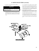
9. Inspect berglass rope located on the swing door. The
rope must be evenly distributed around the perimeter of
the door groove and cannot bunch or overhang. Repair or
replace, if the rope is damaged, or, there is a gap between
the rope ends.
10. Inspect burner swing door insulation for damage and
proper type.
By design, for all models, cast bars on front section
between the combustion chamber, and, between the left
and right side 2
nd
and 3
rd
pass ueways should make an
impression in door insulation to seal the chambers.
By design, door insulation on model MPO-IQ231 will
have two by-pass pockets cast into the insulation centered
on the bar between the combustion chamber and 3
rd
pass
ueways. By design, door insulation on models MPO-
IQ84, MPO-IQ115, MPO-IQ147 and MPO-IQ189 will
not have any by-pass pockets. If insulation is damaged,
or, improper type regarding the pockets, it must be
replaced.
11. Upon inspection completion, lift door and place integral
cast hinge pins into door mounting bracket slotted holes.
Do not close and secure door at this time, proceed to
installing stainless steel ueway bafes.
E. FLUEWAY BAFFLE INSTALLATION. Refer to Section
II, Paragraph F.
F. CLOSING / SECURING BURNER SWING DOOR.
Refer to Section II, Paragraph D.
G. JACKET REAR PANEL INSTALLATION.
1. Locate jacket rear panel (has factory attached 3” berglass
insulation) inside Jacket Carton. See also “Repair
Parts” Section, “Jacket Assembly” illustration for part
identication.
2. Locate and remove from Hardware Bag rear panel
mounting hardware – (2 pcs) 5/16”-18 x 3” lg. tap studs,
(2 pcs) 5/16”-18 plated acorn nuts, (2 pcs) 5/8” x 2-9/32”
round spacers and (2 pcs) 5/16”-18 x ½” Phillips pan head
machine screws.
3. Locate rear panel two lower attachment bosses on rear
section.
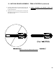
4. Thread both 5/16”-18 x 3” lg. tap studs, with short threaded
end, into lower attachment bosses on rear section.
5. Install both 5/8” x 2-9/32” round spacers over tap
studs.
6. Place rear jacket panel over rear section, so both tap
studs clear thru lower panel holes, rear section cleanout
openings clear thru matching panel cut-outs and brass
sample port plug clears panel matching hole.
7. Secure panel bottom to studs with acorn nuts hand
tight.
8. Align upper panel attachment holes with smokebox upper
attachment bosses and install 5/16”-18 x ½” Phillips pan
head machine screws hand tight.
9. Securely tighten rear jacket panel mounting hardware.
H. FLUE CLEANOUT COVERS AND SMOKEBOX
COLLAR INSTALLATION.
1. Remove two cast iron Cleanout Covers, cast iron
Smokebox Collar and the tube of hi-temperature silicon
adhesive sealant from Part Carton. See also “Repair
Parts” Section, “Bare Boiler Assembly” illustration for
part identication.
2. Check the rope gasket factory attached to the covers.
Repair or replace, if the rope is damaged, or, there is a
gap between the rope ends.
3. Locate/remove four 5/16”-18 – 7/8” hex head cap screws
from Hardware Bag.
4. Apply a drop of supplied Anti-seize (pouch provided
in Part Carton) to each of four (4) 5/16”-18 x 7/8” hex
head cap screws for rust protection and to facilitate easy
removal for future service.
III. UNIT-PAK BOILER ASSEMBLY - TRIM & CONTROLS (continued)