
Install Instructions


34
VI. DIRECT VENTING / AIR INTAKE PIPING
(Boiler Models MPO-IQ147 thru 231 ONLY)
A. GENERAL GUIDELINES
1. Direct Vent system must be installed in accordance with
these instructions and applicable provisions of local
building codes. Contact your local re and building
officials on specific requirements for restrictions
and the installation of fuel oil burning equipment. In
addition, for boiler installation in United States, consult
with a professional knowledgeable on requirements of
NFPA 31- Standard for the Installation of Oil-Burning
Equipment and NFPA211- Standard for Chimney,
Fireplaces, Vents and Solid Fuel-Burning Appliances,
latest editions. Installations in Canada must be reviewed
with a professional knowledgeable on requirements of
CSA B139 – Installation Code for Oil-Burning Equipment,
latest edition.
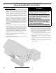
2. In the Direct Vent conguration, all air for combustion
is supplied directly to the burner from outdoors, and, ue
gases are vented directly outdoors (thru wall), via Direct
Vent System (FDVS), which is a non-positive pressure vent
system termination for oil-red appliances, that provides
an outlet for products of combustion, and, an intake for
combustion air in a single concentric terminal.
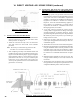
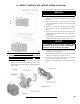
3. Direct Vent Hood Assembly minimum clearance to
combustible material is 0".
4. Maximum wall thickness that FDVS vent termination
may be installed through is 12".
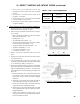
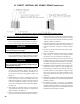
Figure 18: Vent Terminal Location
WARNING
This venting system must be installed by a
qualied installer (an individual who has been
properly trained) or a licensed installer.
DO NOT locate vent termination where exposed
to prevailing wind. Moisture and ice may
form on surfaces around vent termination. To
prevent deterioration, surface must be in good
repair (sealed, painted etc.).
DO NOT locate vent termination where petroleum
distillates, CFC's, detergents, volatile vapors or
any other chemicals are present. Severe boiler
corrosion and failure will result.
DO NOT locate vent termination under a deck.
5. Locate the vent terminal so vent pipe is short and direct,
and, at the place on exterior wall that complies with the
minimum distances as specied in Figure 18 and listed
as follows. The vent termination must be located (as
measured to the bottom of vent terminal):
a. Not less than 12" above nished grade or expected
snow accumulation line whichever is greater.
b. Not less than 3 ft above any forced air inlet located
within 10 ft.
c. Not less than 1 ft from any door, window or gravity
air inlet.
d. Not less than 7 ft above grade when located above
public walkway.