
Install Instructions


53
X. OPERATING (continued)
the trial for ignition, the oil primary control will shut
the burner down and enter into a hard lockout. The Oil
Primary must be reset manually before the burner can be
restarted.
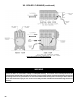
B. USING BOILER CONTROL
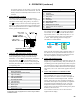
The Boiler Control is located under the Jacket Front
Cover, to the left of the Option Panel (Refer to Figure 33).
The Boiler Control display, along with Up ñ, Down ò,
and “I” keys may be used to view boiler operating status
(Figure 34). Please note that these keys look similar to the
keys on the Option Panel but are in a different orientation,
and they perform different functions.
Status Number Displayed in STA Mode
1 Standby
4* Pre-purge
6* Trial for Ignition
7* Carry Over
8 Running
9* Post-purge
10* Retry/Recycle Delay
14* Hard Lockout
15* Waiting for Limit to Close
16* Flame Present Out of Sequence
17 Self Test
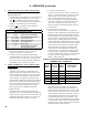
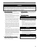
For example, when the “I” key is pressed on the Boiler
Control until “bt” is displayed, it will then ash a three
digit number (such as “180”) followed by either “F” (or
“C”). This indicates that the boiler water temperature
is 180°F. Other operating parameters display the
information in a similar fashion.
Unit Display
OR
Sample
Display
1 sec
1 sec
1 sec
Please note that in operating mode to hold the display on
the value the user can press and hold either the Up ñ or
Down ò keys and the value will be continuously shown.
This may be helpful in watching a value “live”.
D. USING THE OPTION PANEL
Option Cards are available from distributors and are the
simplest way to add functionality, safety and efciency to
your heating system. The Option Panel provides an easy and
convenient means to "plug-in" an Auxiliary High Limit, Low
Water Cut-off and/or Outdoor Reset function. For operating
instructions, refer to the instructions supplied with those
cards.
E. USING THE OPTIONAL LCD DISPLAY KIT
(P/N 102728-01)
The LCD Display is an easy to use touch screen type
display that allows a technician to monitor and adjust the
Boiler Control and connected Option Cards. All boiler
settings, status and error codes are displayed in full text.
All Outdoor Reset Option Card parameters are adjustable
with graphic and help information screens. The LCD
Display Kit includes a mounting bracket and a simple
plug-in wiring connection to allow mounting in the plastic
hood above the burner door.
For installation instructions, refer to the instructions
supplied with the display.
Figure 34: Boiler Control
Key Function & Orientation
C. VIEWING THE OPERATING MODE OPTIONS
In operating mode the user may view (but not change)
boiler operating status, settings and troubleshooting
information. To view Boiler Control display information:
Press and release the “I” key on the Boiler Control to
change from one parameter to the next. Each setting will
alternately ash between the relevant display code and its
corresponding value.
Operating Mode Options
StA Status (see Status Number in following Table)
bt Boiler Temperature
SP Operating Setpoint (Outdoor Reset)
HL High Limit Setting
HdF High Limit Differential
hr Heat Request Status
dh Zone Request Status
CAD* CAD Cell Ohms
rUn* Run Time Hours
CYC* Boiler Cycles
Err Boiler Error
Erp External Device Error
* Visible when Burner-ECOM Harness is connected to
EnviraCOM primary equipped burner. Refer to Figure 28B for
installation details.