
Install Instructions

63
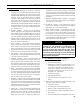
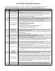
Possible ERP (External Error) Values:
Display Status Recommended Corrective Actions
Err 1 Temperature Sensor Fault
Temperature sensor failure, wire harness loose or shorted connection or control
hardware failure:
- Check sensor is securely attached to boiler control
- Check that sensor wire is not damaged
- If secure and in good condition, replace sensor
- If problem persists, replace control
Err 2 Communication Fault
Enviracom terminal is shorted to ground or line voltage.
- Check wiring to EnviraCOM terminals 1,2 and 3. Wiring to external EnviraCom
device is incorrect.
Err 3 Internal Hardware Fault
Error detected with AC power supply frequency or boiler control failure. Cycle power to
the control. Replace control if problem persists.
Err 4 Burner Output (B1) Fault
B1 output sensed powered during safety output relay check sequence or un-powered
during running, or powered in idle in combination with water temperature above 264°F
limit. Cycle power to the control. Replace control if problem persists.
Err 5 Line Voltage Fault (< 80 Vac) AC voltage out of specication high or low; check L1, L2, 110 VAC.
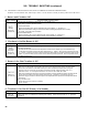
Err 6 Fuse missing
Internal fuse is blown or missing. The fuse protects the Aquastat from miss wiring the
L1 and L2 on Oil Primary. When the Oil Primary is correctly wired the fuse is useless
and not detected. If Primary is wired incorrectly the fuse is blown out and Aquastat
report error 6. EnviraCOM message is sent when the wiring is xed and the error
disappears to indicate the end of the error state. Check wiring and replace fuse.
Err 7
User settings lost, (reset to
factory defaults)
Warning: Generated if user adjustments are lost and the device uses factory default
values. Error is cleared by entering and exiting the Adjustment mode. Replace control
if problem persists.
Err 8
Manual Reset Lockout
(resettable)
Set if Err 4 was invoked four times in a row. Check wiring and clear Lockout by
pressing all three user keys for 30 seconds.
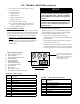
XIII. TROUBLE SHOOTING (continued)
E. USE BOILER CONTROL DISPLAY ERR AND ERP NUMBERS TO DIRECT TROUBLESHOOTING
If the Boiler Control detects an error it will ash "Err" (boiler control error) or "ErP" (external error) followed by a number.
Use this text and number to identify the boiler problem and corrective action in the table below. If there is no error display
proceed to Paragraph E:
TABLE 14A: BOILER CONTROL ERROR NUMBERS
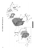
make sure that they are tight. Also, check the wiring
on the boiler against the wiring diagram in Figures
28A, 28B and 28C. Ensure that incoming 120 Vac
power polarity is correct and that the boiler is properly
grounded.
4. A defective control or component is generally the least
likely cause. Before replacing a component, try to rule
out all other possible causes.
5. When checking voltage across wiring harness pins
be careful not to insert the meter probes into the pins.
Doing so may damage the pin, resulting in a loose
connection when the harness is reconnected.
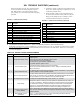
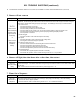
ErP
Value
Description
4 Warning, Cad Cell Resistance High (Service Required)
5 No Ignition, Check Cad Cell
9 Warning, Flame Proven, Late in Trial
10 No Ignition, Check Ignition Transformer
18 Internal Error, Electronics Failure
20 No Ignition
21 No Ignition, After Flame Loss During Run
22 Flame Lost During Run Three Times In A Row
23 Flame Out of Sequence, During Pre-Purge
24 Flame Out of Sequence, During Post-Purge
25 Oil Primary Lockout, Manual Reset Required
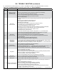
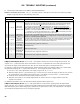
ErP
Value
Description
34 Cad Ohms Permanently Low (Flame Out of Sequence)
35 Duplicate Zone
58 AC Line Frequency Error
59 AC Line Voltage Error
84 Low Water Event
89 Communication Lost
91 Communication Error
119 Sensor Failure
140 Low Probe Signal
141 Manual Reset Lockout
Possible ERP (External Error) Values (continued):