
Install Instructions

84
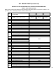
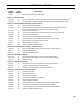
Boiler
Model
Burner
Input
(GPH)
Burner
Model
Nozzle
Head
Setting
Air
Setting
Pump
Pressure
(PSI)
Air Tube
Type
Insertion
Depth
(Inch)
Approx.
Shipped
CO
2
(%)
Bafe
Location
(pass)
Approx.
Stack Temp.
Increase
Without
Bafes °F
(2)
Approx.
Breech
Pressure
(" w.c.)
(3)
Bafes IN
Approx.
Overre
Pressure
(" w.c.)
(3)
Bafes
OUT
Approx.
Overre
Pressure
(" w.c.)
(3)
MPO-IQ84 0.60 EZ-LF
0.50 x 60AS
Danfoss
1.0 30 150 12D 2-5/8 11.5 3
rd
52 0 +0.040 +0.020
MPO-IQ115 0.82 EZ-LF
0.65 x 60AS
Danfoss
0.75 65 150 12D 2-5/8 11.5 2
nd
& 3
rd
84 0 +0.040 +0.020
MPO-IQ147 1.05 EZ-66
0.85 x 45AS
Danfoss
2.0 40 150
Conical
Wrap
2-5/8 11.5 2
nd
65 0 +0.040 +0.020
MPO-IQ189 1.35 EZ-66
1.10 x 45B
Delavan
3.5 50 150
Conical
Wrap
2-5/8 11.5 2
nd
39 0 +0.040 +0.030
MPO-IQ231 1.65 EZ-66
1.35 x 45B
Hago
5.5 60 150
Conical
Wrap
2-5/8 11.5 2
nd
18 0 +0.050 +0.030
Notes
(2)
The increased stack temperature with the bafes removed is an approximation, based on a constant supply temperature of 180°F and 11.5% CO
2
. Actual eld
conditions may be different.
(3)
These values are minimum and could be as much as -.03" w.c., more without impacting performance. Pressures based on 11.5% CO
2
. Example: MPO-IQ231
could have a breech pressure of -.03" w.c. and an overre pressure of .020" w.c.
4) Single stage fuel pump is standard, two-stage fuel pump is optional. Burner manufacturer has preset single stage fuel pump to settings shown in table above.
Two-stage fuel pump is factory set at 140 PSI and must be readjusted to settings shown above during burner start-up.
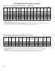
TABLE 15C: CARLIN EZ BURNER SPECIFICATIONS - CHIMNEY VENT
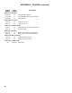
TABLE 16: BECKETT NX BURNER SPECIFICATIONS - DIRECT VENT
Boiler Model
Burner
Input
(GPH)
Head /Air
Adjustment
(setting)
Nozzle
Pump
Pressure
(PSI)
Approx.
Shipped
CO
2
(%)
Bafe
Location
(pass)
Approx. Stack
Temp. Increase
Without Bafes
°F
(2)
Bafes
IN
Minimum
Overre
Pressure
(" w.c.)
(3)
Bafes OUT
Minimum
Overre
Pressure
(" w.c.)
(3)
Bafes
IN
Minimum
Breech
Pressure
(" w.c.)
(3)
Bafes
OUT
Minimum
Breech
Pressure
(" w.c.)
(3)
MPO-IQ147 1.05 2.75
0.75 - 60°W
Delavan
180 11.5 2
nd
75 +0.06 +0.045 +0.045 +0.03
MPO-IQ189 1.35 1.00
1.00 - 45°B
Hago
180 11.5 2
nd
70 +0.10 +0.05 +0.08 +0.04
MPO-IQ231 1.65 2.25
1.25 - 45°B
Hago
180 11.5 2
nd
23 +0.07 0 +0.06 +0.02
Notes
(2)
The increased stack temperature with the bafes removed is an approximation, based on a constant supply temperature of 180°F and 11.5% CO
2
.
Actual eld values may be different.
(3)
These values are representative for max vent and air intake piping conditions @ 180°F supply water temperature and 11.5% CO
2
. Actual eld values
may be different.
4) Single stage fuel pump is standard, two-stage fuel pump is optional. Burner manufacturer has preset single stage fuel pump to settings shown in
table above. Two-stage fuel pump is factory set at 140 PSI and must be readjusted to settings shown above during burner start-up.
XV. BURNER SPECIFICATIONS (continued)