
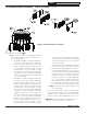
Product Overview


16
103859-12 - 8/19
MPO-IQ
Installation & Service Manual
NPT tapping on tee. See Figure 5.
Step c. Pipe discharge of relief valve as shown in
Figures 10 and 11. Installation of the relief valve
must be consistent with ANSI/ASME Boiler and
Pressure Vessel Code, Section IV.
WARNING
Safety valve discharge piping must be piped near
floor to eliminate potential of severe burns. Do not
pipe in any area where freezing could occur. Do
not install any shut-off valves, plugs or caps.
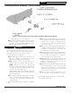
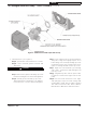
2. Install drain valve, see Figure 6.
Step a. Apply pipe sealant to both ends of 1-1/4"
NPT x 5" lg. nipple. Thread nipple into 1-1/4"
NPT lower rear tapping on rear section.
Step b. Thread 1-1/4" x 1-1/4" x 3/4" NPT tee on
opposite end of 5" lg. nipple installed in Step a.
NOTE: Based on access for servicing and
location of sewer or floor drain, when tightening
these fittings, determine if drain valve is to be
located on the left or right side.
Tighten nipple and tee into 1-1/4" NPT lower rear
tapping on rear section until joints are water tight
for desired position.
Step c. Apply sealant to 3/4" NPT thread on drain
valve. Thread into 3/4" NPT tapping on side
outlet of tee. Use hex nut portion to tighten valve
until water tight.
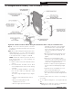
3. Connecting field wiring, refer to Figures 7, 28A thru
28C.
Step a. Locate the black, white and green harness
wires labeled "120V Power Supply" inside internal
junction box, see Figure 7. Using wire nuts,
connect the 120 volt power supply field wires
to the harness wires.
Step b. Locate the yellow and white wires labeled
"System Circulator" inside internal junction box,
see Figure 7. Using wire nuts, connect the 120
volt field wires to the harness wires.
Step c. If applicable, locate the violet and white wires
labeled "DHW Circulator" inside internal junction
box, see Figure 7. Using wire nuts, connect the
120 volt field wires to the harness wires.
Step d. If applicable, locate the brown wire labeled
"DHW Demand" inside internal junction box, see
Figure 7. Using wire nut, connect the 120 volt
field wire to the harness wire.
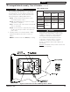
Step e. 24V thermostat field wiring will enter through
5/16" snap bushing located on either the right
side or left side jacket panel. Connect the 24V
wiring from the thermostat to the "T-T" terminals
on the Option Control Panel.
Step f. To connect other external devices, refer
to the instructions included with these devices.
4. Installing Boiler-ECOM harness (only used with
Honeywell Oil Primary).
Figure 6: Piping Arrangement for Drain Valve and Indirect Water Heating Return
2 Packaged Boiler Assembly - Trim & Controls (continued)
!