
Product Overview


17
103859-12 - 8/19
MPO-IQ
Installation & Service Manual
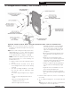
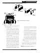
Figure 7: Internal Junction Box and Wiring Harness Details
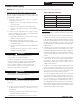
Boiler Model
No.
Baffle Usage
2
nd
Pass 3
rd
Pass
Combustion
Chamber
MPO-IQ84B
[2]
P/N 102066-01
None None
MPO-IQ115B
[2]
P/N 109902-01
[2]
P/N 100081-01
[1]
P/N 109901-01
MPO-IQ147B
[2]
P/N 100042-01
None NoneMPO-IQ189B
MPO-IQ231B
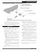
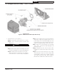
Step a. Locate the black Cat5 harness in the
miscellaneous parts carton.
Step b. Plug RJ45 plug into receptacle on right
side panel, see Figure 1.
Step c. Connect other end of harness into ECOM
jack on Oil Primary.
Step d. Secure harness to right side jacket using
the two wire clamps located in miscellaneous
parts carton.
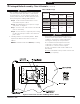
5. Installing stainless steel flueway baffles. Baffle
requirements differ from model to model, see
Table 3.
NOTE: Read caution statement before proceeding.
Table 3: Baffle Usage
2 Packaged Boiler Assembly - Trim & Controls (continued)
CAUTION
These baffles will generate higher efficiencies
and lower stack temperatures. Under certain
conditions, a lower gross stack temperature
entering the chimney has the potential to
be cooled below the dew point and create
condensate on interior surfaces. Flue gas
condensate is corrosive, which requires
special consideration and must be addressed
immediately.
DO NOT install baffles until you have read Section
IV, "Venting" completely.
!
WARNING
Wire an additional safety limit such as a low water
cut-off or temperature limit device, other than an
IQ Control device, in series with the 120V circuit
used to power the boiler. Do Not alter the boiler's
factory wiring when adding additional limit.
!