
Product Overview


34
103859-12 - 8/19
MPO-IQ
Installation & Service Manual
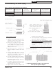
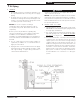
13. Mount the assembled vacuum relief valve gate with
balance weight into the tee and fasten with a screw
and nut in collar tabs. To insure proper operation, the
gate must be level across the pivot point and plumb.
Refer to the vacuum relief valve manufacturer’s
instructions for details.
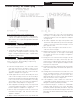
14. Install remainder of air intake piping to Direct
Vent Termination air intake collar, securing each
joint with at least (3) sheet metal screws (installer
provided) evenly spaced.
15. Maintain ¼” per foot slope in horizontal run to air
intake of Direct Vent Termination.
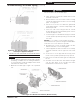
16. Support the air intake piping, as required, using
perforated metal strap or other supports.
17. Refer to Burner Manufacturer's Manual for
addition information.
5 Direct Venting / Air Intake Piping (continued)