Installation, Operating and Service Instructions for MPO-IQ TM Models: • MPO-IQ84B • MPO-IQ115 B • MPO-IQ147 B • MPO-IQ189 B • MPO-IQ231B • High Efficiency • Oil-Fired, 3-Pass • Water Boiler • Natural Draft or Direct Vent (147B thru 231B) Manual Contents Page Pre-installation. . . . . . . . . . . . . . . . . . . . . . . . . . 8 Packaged Boiler Assy. - Trim & Controls. . . . 11 Water Boiler Piping. . . . . . . . . . . . . . . . . . . . .
MPO-IQ Installation & Service Manual IMPORTANT INFORMATION - READ CAREFULLY All boilers must be installed in accordance with National, State and Local Plumbing, Heating and Electrical Codes and the regulations of the serving utilities. These Codes and Regulations may differ from this instruction manual. Authorities having jurisdiction should be consulted before installations are made. In all cases, reference should be made to the following Standards: USA BOILERS A.
MPO-IQ ! Installation & Service Manual DANGER DO NOT store or use gasoline or other flammable vapors or liquids in the vicinity of this or any other appliance. ! WARNING Improper installation, adjustment, alteration, service or maintenance can cause property damage, personal injury or loss of life. Failure to follow all instructions in the proper order can cause personal injury or death.
MPO-IQ Installation & Service Manual ! WARNING This boiler must be properly vented. The chimney must be inspected for any obstructions and cleaned prior to each heating season. A clean and unobstructed chimney flue is necessary to produce the minimum draft required to safely evacuate noxious fumes that could cause personal injury or loss of life. Evidence of loose debris and or condensate induced stains at the base of the chimney flue, connector or smokepipe joints may be signs of condensing flue gases.
MPO-IQ Installation & Service Manual Congratulations on your purchase of a new MPO-IQ™ boiler—designed and constructed to provide you with years of reliable service. • Cast iron heat exchanger – for reliability and durability, nothing beats a cast iron heat exchanger. • *IQ Control™ System – the most advanced and easiest to use controls available. • System-friendly – built-in protection from condensation and thermal shock.
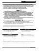
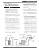
Installation & Service Manual Figure 1: MPO-IQ Water Boiler MPO-IQ 6 103859-12 - 8/19
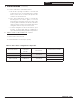
Installation & Service Manual MPO-IQ Table 1A: Dimensional Data (See Figure 1) Boiler Model No. Dimensions See Figure 1 Water Content - Gallons Heat Transfer Surface Area Sq. Ft. Actual Shipping Weight (LB.) “A” “B” “C” MPO-IQ84B/115B 16-5/8” 24” 5” 7.70 13.29 430 MPO-IQ147B 22-5/8” 24” 6” 11.08 20.29 545 MPO-IQ189B 28-5/8” 30” 6” 14.46 27.29 658 MPO-IQ231B 34-5/8” 36” 7” 17.84 34.29 771 NOTE: 1.
MPO-IQ Installation & Service Manual 1 Pre-Installation A. INSPECT SHIPMENT carefully for any signs of damage. 1. All equipment is carefully manufactured, inspected and packed. Our responsibility ceases upon delivery of crated boiler to the carrier in good condition. 2. Any claims for damage or shortage in shipment must be filed immediately against the carrier by the consignee.
MPO-IQ 1 Pre-Installation (continued) C. PROVIDE COMBUSTION AND VENTILATION AIR. Local and National Codes may apply and should be referenced. ! WARNING Adequate combustion and ventilation air must be provided to assure proper combustion and to maintain safe ambient air temperatures. Do not install boiler where gasoline or other flammable vapors or liquids, or sources of hydrocarbons (i.e. bleaches, fabric softeners, etc.) are used or stored. 1. Determine volume of space (boiler room).
MPO-IQ Installation & Service Manual 1 Pre-Installation (continued) 6. Louvers and Grilles of Ventilation Ducts a. All outside openings should be screened and louvered. Screens used should not be smaller than 1/4 inch mesh. Louvers will prevent the entrance of rain and snow. b. Free area requirements need to consider the blocking effect of louvers, grilles, or screens protecting the openings.
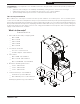
MPO-IQ Installation & Service Manual 2 Packaged Boiler Assembly - Trim & Controls A. REMOVE CRATE. 1. Remove all fasteners at crate skid. 2. Lift outside container and remove all other inside protective spacers and bracing. Remove miscellaneous parts carton. B. REMOVE BOILER FROM SKID. 1. To reduce the risk of damage to boiler jacket, use the following procedure to remove from skid, see Figure 3: Step 1.
MPO-IQ Installation & Service Manual 2 Packaged Boiler Assembly - Trim & Controls (continued) Figure 4A: Partial Front View - Burner Swing Door Mounted to Boiler - Fully Closed and Secured retaining screw (5/16" x 1/2" lg. Phillip Step 4. Disconnect burner power cord from Pan head machine screw) from right receptacle located in lower right corner of jacket side of door and re-install in vacated front panel. upper mounting bracket tapping. Do Step 5.
MPO-IQ Installation & Service Manual 2 Packaged Boiler Assembly - Trim & Controls (continued) Figure 4B: Top View - Burner Swing Door Mounted to Cast Iron Block Assembly (Jacket Removed for Clarity) 103859-12 - 8/19 13
MPO-IQ Installation & Service Manual 2 Packaged Boiler Assembly - Trim & Controls (continued) Step 2. If necessary, place your right hand under the burner air tube to lift upward. Lift the door up unto the built-in cast ramp/door rest (protruding from the bottom of the front section casting - see Figure 4A). E. INSPECT SWING DOOR INSULATION AND ROPE GASKET. 1. Open burner swing door using procedure previously outlined in Paragraph D of this section. 2. Inspect fiberglass rope located on the swing door.
MPO-IQ Installation & Service Manual 2 Packaged Boiler Assembly - Trim & Controls (continued) Figure 4D: Burner Swing Door Insulation Step a. Locate the return pipe fittings and injector. Apply sealant to the 2” NPT injector threads. Insert injector into 2” NPT upper rear tapping on rear section. Thread 2” NPT x 1-1/2” Reducing Elbow onto 2” NPT injector. Apply thread sealant to the 1-1/2” NPT nipple. Thread 1-1/2” NPT nipple into 1-1/2” NPT end of reducing elbow.
MPO-IQ Installation & Service Manual 2 Packaged Boiler Assembly - Trim & Controls (continued) Figure 6: Piping Arrangement for Drain Valve and Indirect Water Heating Return NPT tapping on tee. See Figure 5. Step c. Pipe discharge of relief valve as shown in Figures 10 and 11. Installation of the relief valve must be consistent with ANSI/ASME Boiler and Pressure Vessel Code, Section IV. ! WARNING Safety valve discharge piping must be piped near floor to eliminate potential of severe burns.
MPO-IQ Installation & Service Manual 2 Packaged Boiler Assembly - Trim & Controls (continued) ! WARNING Wire an additional safety limit such as a low water cut-off or temperature limit device, other than an IQ Control device, in series with the 120V circuit used to power the boiler. Do Not alter the boiler's factory wiring when adding additional limit. Table 3: Baffle Usage Boiler Model No. Baffle Usage 2nd Pass 3rd Pass Combustion Chamber Step a.
MPO-IQ Installation & Service Manual 2 Packaged Boiler Assembly - Trim & Controls (continued) Figure 8: Baffle Orientation in Flueways Step a. Install stainless steel baffles provided in miscellaneous parts carton as follows, refer to Table 3 and Figure 8: • • 18 Model MPO-IQ84B - To install flueway baffle in 2nd pass on left side of boiler, hold baffle with word "Left" readable at the top. Slide baffle in flueway until position tab touches fins on left side of 2nd pass flueway.
MPO-IQ Installation & Service Manual 2 Packaged Boiler Assembly - Trim & Controls (continued) Figure 9: Oil Burner Installation (Beckett shown) 7. Install oil burner. (See Figure 9) Step a. Open burner carton and remove contents. Step b. Place oil burner gasket on burner and align holes. ! CAUTION Do not install burner without gasket. Step c. Remove three (3) 5/16-18 x 3/4 lg. cap screw from burner swing door used for mounting burner. Step d. Thread (1) 5/16-18 x 3/4 lg.
MPO-IQ Installation & Service Manual 3 Water Boiler Piping NOTICE Failure to pipe boiler as specified in this manual may result in excessive system noise. A. EVALUATE THE EXISTING WATER SYSTEM. Design a piping system and install boiler which will prevent oxygen contamination of boiler water and frequent water additions. 1. There are many possible causes of oxygen contamination such as: a. Addition of excessive make-up water as a result of system leaks. b. Absorption through open tanks and fittings. c.
MPO-IQ Installation & Service Manual Figure 10: Recommended Water Piping for Circulator Zoned Heating Systems 3 Water Boiler Piping (continued) 103859-12 - 8/19 21
MPO-IQ Installation & Service Manual Figure 11: Recommended Water Piping for Zone Valve Zoned Heating Systems 3 Water Boiler Piping (continued) 22 103859-12 - 8/19
MPO-IQ Installation & Service Manual 3 Water Boiler Piping (continued) 5. See Figure 12 for suggested near boiler piping of Option Card Controls. ! WARNING The use of a low water cut-off device, while not required unless radiation level is below the boiler, is highly recommended. If a low water cut-off is required, it must be mounted in the supply piping above the boiler (see Figure 12).
MPO-IQ Installation & Service Manual 4 Natural Draft Venting (All Boiler Models) ! WARNING Vent this boiler according to these supplemental instructions. Failure to do so may cause products of combustion to enter the home resulting in severe property damage, personal injury or death. • • Insufficient Combustion Air Supply may result in the production and release of deadly carbon monoxide (CO) into the home which can cause severe personal injury or death.
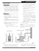
MPO-IQ Installation & Service Manual 4 Natural Draft Venting (continued) Figure 13: Recommended Vent Pipe Arrangement and Chimney Requirements Figure 14: Proper and Improper Locations of Draft Regulator 103859-12 - 8/19 25
MPO-IQ Installation & Service Manual 4 Natural Draft Venting (continued) B. CHIMNEY CONNECTOR 1. A chimney connector (vent pipe) is used to connect the boiler to the base of the chimney. The chimney connector should be kept as short as possible. The horizontal length of the chimney connector shall not be greater than 10 feet. NOTE: Secure chimney connector to cast iron smokebox collar with three (3) #10 x ½" self drilling hex head TEK screws provided in miscellaneous parts carton.
Installation & Service Manual MPO-IQ 4 Natural Draft Venting (continued) temperature outlined in this section can be maintained. (ONLY AVAILABLE WITH BECKETT BURNER). Refer to Section I, Paragraph C, Steps 5 and 6 for optional air intake piping installation information. ! CAUTION Any doubt on the condition of a chimney or it’s ability to prevent the generation and accumulation of flue gas condensate, must be relined according to NFPA 31 (United States) or CSA B139 (Canada).
MPO-IQ Installation & Service Manual 5 Direct Venting / Air Intake Piping (Boiler Models MPO-IQ140E thru 231 ONLY) A. GENERAL GUIDELINES 1. Direct Vent system must be installed in accordance with these instructions and applicable provisions of local building codes. Contact your local fire and building officials on specific requirements for restrictions and the installation of fuel oil burning equipment.
MPO-IQ Installation & Service Manual 5 Direct Venting / Air Intake Piping (continued) f. Not less than 1 ft from the nearest surface of the terminal to a roof soffit. g. Not directly above, or, not less than 5 ft horizontally from an oil tank vent. h. Not less than 2 ft from nearest surface of terminal to an adjacent building. B. INSTALLATION OF THE VENT HOOD TERMINAL 1. Inspect Direct Vent Conversion Kit Carton for damage. DO NOT install if any damage is evident.
MPO-IQ Installation & Service Manual 5 Direct Venting / Air Intake Piping (continued) D. INSTALLING THE FLEX OIL VENT PIPE FROM THE VENT TERMINATION TO THE BOILER FLUE OUTLET 1.
MPO-IQ Installation & Service Manual 5 Direct Venting / Air Intake Piping (continued) Table 6: Flex Vent / Vent Termination Pipe Diameters Boiler Model No.
MPO-IQ Installation & Service Manual 5 Direct Venting / Air Intake Piping (continued) Figure 23: Vent Pipe Ends, Vent Termination and Appliance Adapter Sealing ADAPTER AND DIRECT VENT TERMINATION 1. Flexible double wall oil vent pipe is available precut from 10 ft and 20 ft long. If necessary, the vent pipe may be cut to required length with a hacksaw or cutoff saw. ! CAUTION Use safety glasses and other appropriated safety gear when cutting the vent pipe. 2.
Installation & Service Manual MPO-IQ 5 Direct Venting / Air Intake Piping (continued) ! WARNING DO NOT reduce size of air intake pipe. 3. Start at burner and work towards Direct Vent termination air intake. 4. Remove burner cover. Loosen two screws securing outside air duct bracket to burner cover mounting plate. See Figure 25. 5. Procure a 2-ft section of 4" diameter galvanized single wall vent pipe, cut off the crimped pipe end below stop bead. 6.
MPO-IQ Installation & Service Manual 5 Direct Venting / Air Intake Piping (continued) 13. Mount the assembled vacuum relief valve gate with balance weight into the tee and fasten with a screw and nut in collar tabs. To insure proper operation, the gate must be level across the pivot point and plumb. Refer to the vacuum relief valve manufacturer’s instructions for details. 14.
Installation & Service Manual MPO-IQ 6 Electrical ! DANGER Positively assure all electrical connections are unpowered before attempting installation or service of electrical components or connections of the boiler or building. Lock out all electrical boxes with padlock once power is turned off. ! WARNING Failure to properly wire electrical connections to the boiler may result in serious physical harm. • Electrical power may be from more than one source.
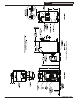
MPO-IQ Installation & Service Manual Figure 26 Schematic Wiring Diagram 6 Electrical (continued) 36 103859-12 - 8/19
MPO-IQ Installation & Service Manual Figure 27: Schematic Wiring Diagram, All Burner Options 6 Electrical (continued) 103859-12 - 8/19 37
MPO-IQ Installation & Service Manual 6 Electrical (continued) Figure 28: Ladder Diagram 38 103859-12 - 8/19
Installation & Service Manual MPO-IQ 7 Oil Piping A. GENERAL ! 1. Use flexible oil line(s) so the burner swing door can be opened without disconnecting the oil supply piping. 2. A supply line fuel oil filter is recommended as a minimum for all firing rates but a pleated paper fuel oil filter is recommended for the firing rates below 1.0 GPH to prevent nozzle fouling. NOTICE Do not use compression fittings. Oil piping must be absolutely airtight or leaks or loss of prime may result.
MPO-IQ Installation & Service Manual 7 Oil Piping (continued) C. TWO PIPE OIL LINES 1. For two piped systems, where more lift is required, the two-stage fuel unit is recommended. Table 7 (two-stage) and Table 8 (single-stage) show allowable lift and lengths of 3/8 inch and 1/2 inch OD tubing for both suction and return lines. Refer to Figure 30. 2. Follow the oil pump manufacturer’s recommendations on the proper connections for a two pipe system. Some manufacturers require the insertion of a bypass plug.
MPO-IQ Installation & Service Manual 8 System Start-Up ! WARNING All boilers equipped with burner swing door have a potential hazard which can cause severe property damage, personal injury or loss of life if ignored. Before opening swing door, turn off service switch to boiler to prevent accidental firing of burner outside the combustion chamber. Be sure to tighten swing door fastener completely when service is completed.
MPO-IQ Installation & Service Manual 8 System Start-Up (continued) 4. Allow burner to run until oil flows from vent fitting is a SOLID stream without air bubbles for approximately 10 seconds. 3. READJUST THE HEAD SETTING. It might be necessary to move the head forward or back one position at a time to optimize the smoke and CO2 readings. Refer to Burner Manufacturer's Manual for details. NOTE: For Primary Control "Pump Priming Cycle" details, see Paragraph J, No. 1., Step b. 4.
Installation & Service Manual MPO-IQ 8 System Start-Up (continued) ! WARNING Before installation of the boiler is considered complete, the operation of all boiler controls must be checked, particularly the primary control and high limit control. J. VERIFY HONEYWELL OIL PRIMARY FEATURES using procedures outlined in Instructions furnished with control or instructions as follows: 1. R7284 FEATURES AND CONTROLS a. The Oil Primary is a microprocessor-based control.
MPO-IQ Installation & Service Manual 8 System Start-Up (continued) • If safety switch shuts down burner and • • • • • resistance is above 1600 OHMS, open line switch to boiler. Access cad cell under ignitor, clean face of cad cell and see that cell is securely in socket, see Figure 32. Check gasket around perimeter of ignitor lid for proper seal. If gasket is missing or damaged, replace gasket. Room light can effect cad cell resistance. Reset safety switch.
MPO-IQ Installation & Service Manual 8 System Start-Up (continued) Important Product Safety Information: Refractory Ceramic Fiber Product WARNING Some boiler components use materials that contain refractory ceramic fibers (RCF). RCF has been classified as a possible human carcinogen. When exposed to elevated temperatures, RCF may change into crystalline silica, a known carcinogen.
MPO-IQ Installation & Service Manual 9 Operating Figure 33: Boiler Control & Option Panel Orientation A. BOILER SEQUENCE OF OPERATION 1. The boiler's sequence of operation is shown in Table 9. 2. When there is a call for heat the boiler control starts the system circulator and the thermal purge (circulator pre-purge time) begins.
Installation & Service Manual MPO-IQ 9 Operating (continued) burner will stop. When water level is replenished, the burner will restart. 8. On burner start, if the cad cell does not see flame during the trial for ignition, the oil primary control will shut the burner down and enter into a hard lockout. The Oil Primary must be reset manually before the burner can be restarted. B.
MPO-IQ Installation & Service Manual 9 Operating (continued) D. USING THE OPTION PANEL Option Cards are available from distributors and are the simplest way to add functionality, safety and efficiency to your heating system. The Option Panel provides an easy and convenient means to "plug-in" an Auxiliary High Limit, Low Water Cut-off and/or Outdoor Reset function. For operating instructions, refer to the instructions supplied with those cards. E.
Installation & Service Manual MPO-IQ 9 Operating (continued) is started and boiler firing is delayed pre-purge minutes. If the temperature drops below 140°F or there is a DHW Call for Heat the boiler is started without delay. Additionally, the boiler is started without delay if the thermostat call for heat is initiated when the boiler water temperature is less than 140°F. This feature helps save energy by satisfying home heating needs with residual boiler heat rather than cycling the boiler.
Installation & Service Manual MPO-IQ 9 Operating (continued) When an Outdoor Air Reset Option Card is installed and there is a DHW call for heat there is an adjustable DHW Temperature Setpoint and Priority Timer included. Refer to Table 11B. b. When is set equal to Zone Request () When there is no IWH the “ZC” output may be configured to control a second heating zone. This is particularly helpful when the home uses only two heating zones.
Installation & Service Manual MPO-IQ 10 Maintenance and Service Instructions A. MAINTENANCE OF LOW DEVICES (when installed) WATER CUT-OFF See Instructions provided with Low Water Cut-off Option Card for Installation Instructions. ! WARNING Probe type low water cut-off devices require annual inspection and maintenance. 1. PROBE TYPE LOW WATER CUT-OFF Although these devices are solid state in their operation, the probe is exposed to possible contamination in the boiler water and subject to fouling.
Installation & Service Manual MPO-IQ 10 Maintenance and Service Instructions (continued) c. Remove relief valve using extreme care to avoid damaging it. d. Add an appropriate amount of recommended boil out compound. e. Replace relief valve. f. Fill the entire system with water. g. Start firing the boiler. h. Circulate the water through the entire system. i. Vent the system, including the radiation. j Allow boiler water to reach operating temperature, if possible. k.
MPO-IQ Installation & Service Manual 11 Boiler Cleaning ! WARNING All boiler cleaning must be completed with burner service switch turned off. Boilers equipped with burner swing door have a potential hazard which can cause severe property damage, personal injury or loss of life if ignored. Before opening swing door, turn off service switch to boiler to prevent accidental firing of burner outside the combustion chamber. Disconnect the burner plug from the receptacle in the front jacket.
MPO-IQ Installation & Service Manual 11 Boiler Cleaning (continued) Figure 35: Cleaning of Boiler Flueways ! WARNING This boiler contains controls which may cause the boiler to shut down and not restart without service. If damage due to frozen pipes is a possibility, the heating system should not be left unattended in cold weather; or appropriate safeguards and alarms should be installed on the heating system to prevent damage if the boiler is inoperative.
MPO-IQ Installation & Service Manual 12 Troubleshooting A. COMBUSTION 1. NOZZLES — Although the nozzle is a relatively inexpensive device, its function is critical to the successful operation of the oil burner. The selection of the nozzle supplied with the MPO-IQ boiler is the result of extensive testing to obtain the best flame shape and efficient combustion. Other brands of the same spray angle and spray pattern may be used but may not perform at the expected level of CO2 and smoke.
MPO-IQ Installation & Service Manual 12 Troubleshooting (continued) c. Defective nozzle causing flame to be erratic. d. Excessive airflow or draft causing flame to leave burner head. e. Excessive back pressure causing flame to be erratic. 3. Control locks out after Trial For Ignition (TFI). a. No oil to burner. b. Shorted electrodes. c. Nozzle clogged. d. Airflow too high. e. Ignitor module defective. f. CAD cell defective. g. Oil valve stuck open or closed.
MPO-IQ Installation & Service Manual 12 Troubleshooting (continued) 4. A defective control or component is generally the least likely cause. Before replacing a component, try to rule out all other possible causes. Possible ErP (External Error) Values: 5. When checking voltage across wiring harness pins be careful not to insert the meter probes into the pins. Doing so may damage the pin, resulting in a loose connection when the harness is reconnected.
MPO-IQ Installation & Service Manual 12 Troubleshooting (continued) E. USE BOILER CONTROL DISPLAY AND ERP NUMBERS TO DIRECT TROUBLESHOOTING (continued) Table 14B: External Device (Oil Primary, Option Card, etc.
MPO-IQ Installation & Service Manual 12 Troubleshooting (continued) E. USE BOILER CONTROL DISPLAY AND ERP NUMBERS TO DIRECT TROUBLESHOOTING (continued) Table 14B: External Device (Oil Primary, Option Card, etc.) Error Numbers (continued) Display Status Recommended Corrective Actions ErP 23 Flame was proven during the valve on delay period. Check the oil valve for proper Flame Out of Sequence, operation. During Pre-Purge If the system does not have an oil valve, set the valve on delay to 0.
MPO-IQ Installation & Service Manual 12 Troubleshooting (continued) F. USE BOILER CONTROL DISPLAY STA (STATUS) NUMBER TO GUIDE TROUBLESHOOTING The Boiler Control will flash “” followed by a number. Use this number to identify the boiler problem in the table below: 1. Burner and Circulator Off Display / Status Recommended Corrective Action The boiler has not detected a call for heat (hr = off and dh = off). Ensure there is power to the boiler control.
MPO-IQ Installation & Service Manual 12 Troubleshooting (continued) F. USE BOILER CONTROL DISPLAY STA (STATUS) NUMBER TO GUIDE TROUBLESHOOTING (continued) 5. Burner will not come on Display / Status Recommended Corrective Action When a hard lockout occurs the burner shuts down and will not restart until the Oil Primary’s manual reset button is pressed.
MPO-IQ Installation & Service Manual 12 Troubleshooting (continued) G.
MPO-IQ Installation & Service Manual 13 Service Parts All MPO-IQ™ Boiler Service Parts may be obtained through your local U.S. Boiler Company Wholesale distributor. Should you require assistance in locating a U.S. Boiler Company Distributor in your area, or have questions regarding the availability of U.S. Boiler Company products or service parts, please contact U.S. Boiler Company Customer Service at (717) 4818400 or Fax (717) 481-8408.
MPO-IQ Installation & Service Manual Bare Boiler Assembly 13 Service Parts (continued) 64 103859-12 - 8/19
MPO-IQ Installation & Service Manual 13 Service Parts (continued) MPO-IQ Bare Boiler Assembly Item No.
MPO-IQ Installation & Service Manual 2D 2G 2C 2E 2F 2A MPO-IQ Water Boilers - Trim 2H 2B 13 Service Parts (continued) 66 103859-12 - 8/19
MPO-IQ Installation & Service Manual 13 Service Parts (continued) MPO-IQ Water Trim Item No 2A Description Complete Jacket Carton Includes: Labels and Hardware Part Number MPO-IQ84B 103069-02 1 MPO-IQ115B MPO-IQ147B MPO-IQ189B 1 103069-03 1 103069-04 1 103069-05 109553-02 2B 1 1 1 109553-03 Wrap Around Insulation MPO-IQ231B 1 109553-04 1 109553-05 1 2C Plastic Cover 109643-01 1 1 1 1 1 2D Temperature & Pressure Gauge 105894-01 1 1 1 1 1 2E Immersion Well 109644-
MPO-IQ Installation & Service Manual 4C 4E 4D 4A MPO-IQ84 Thru MPO-IQ231 Water Boilers - Trim and Controls 4B 4F 13 Service Parts (continued) 68 103859-12 - 8/19
MPO-IQ Installation & Service Manual 13 Service Parts (continued) MPO-IQ Controls Item No.
MPO-IQ Installation & Service Manual 13 Service Parts (continued) Item No. Description Part No. MPO-IQ147B MPO-IQ189B MPO-IQ231B 5.
MPO-IQ Installation & Service Manual 13 Service Parts (continued) Item No Description Part Number MPO-IQ84B 105406-02 1 104507-02 Natural Draft MPO-IQ115B MPO-IQ147B 1 104508-03 1 104509-04 Beckett MPO-IQ189B MPO-IQ231B 1 104510-05 1 103896-03 Direct Vent 1 109897-04 1 103898-05 102276-01 Not Carlin Shown 1 1 102276-02 Natural Draft 1 102276-03 1 102276-04 1 102276-05 103143-01 1 1 103143-02 Riello Natural Draft 1 100831-01 1 101762-01 1 101763-01 Primary Control Ho
MPO-IQ Installation & Service Manual Beckett AFG Burner 13 Service Parts (continued) 72 103859-12 - 8/19
MPO-IQ Installation & Service Manual 13 Service Parts (continued) BECKETT AFG OIL BURNER PART NOS. FOR MPO-IQ SERIES BOILERS NATURAL DRAFT APPLICATIONS NOTE: When ordering parts always give the serial and model numbers shown on the boiler and burner. Also provide the name of the part(s) and part number as listed below.
MPO-IQ Installation & Service Manual Beckett NX Burner 13 Service Parts (continued) 74 103859-12 - 8/19
MPO-IQ Installation & Service Manual 13 Service Parts (continued) BECKETT NX OIL BURNER PART NOS. FOR MPO-IQ SERIES BOILERS DIRECT VENT APPLICATIONS NOTE: When ordering parts always give the serial and model numbers shown on the boiler and burner. Also provide the name of the part(s) and part number as listed below. Item No.
MPO-IQ Installation & Service Manual 13 Service Parts (continued) RIELLO OIL BURNER PART NUMBERS FOR MPO-IQ SERIES BOILERS NOTE: When ordering parts always give the serial and model numbers shown on the boiler and burner. Refer to Models F3 & F5 Installation Manual, Riello 40 Series Residential Oil Burners (C6501010) or Model F10 Installation Manual, Riello 40 Series Residential Oil Burners (2902554) for an exploded view of the burner and a list of spare parts.
Installation & Service Manual MPO-IQ 14 Burner Specifications Table 15A: Beckett AFG Burner Specifications - Chimney Vent Boiler Model Burner Input (GPH) Burner Model MPO-IQ84B 0.60 AFG MPO-IQ115B 0.80 AFG MPO-IQ147B 1.00 AFG MPO-IQ189B 1.30 AFG MPO-IQ231B 1.60 AFG Nozzle Baffle Location (pass) Approx. Stack Temp. Increase Without Baffles °F (2) Approx. Breech Pressure (" w.c.) (3) Baffles IN Approx. Overfire Pressure (" w.c.) (3) Baffles OUT Approx. Overfire Pressure (" w.c.
Installation & Service Manual MPO-IQ 14 Burner Specifications (continued) Table 15C: Carlin EZ Burner Specifications - Chimney Vent Boiler Model Burner Input (GPH) Burner Model MPO-IQ84B 0.60 EZ-LF MPO-IQ115B 0.80 EZ-LF MPO-IQ147B 1.00 EZ-66 MPO-IQ189B 1.30 EZ-66 MPO-IQ231B 1.60 EZ-66 Nozzle 0.50 x 60AS Danfoss 0.65 x 60AS Danfoss 0.85 x 45AS Danfoss 1.10 x 45B Delavan 1.35 x 45B Delavan Approx. Breech Pressure (" w.c.) (3) Baffles IN Approx. Overfire Pressure (" w.c.
MPO-IQ Installation & Service Manual Appendix A - Oil Burner IQ Control System IQ Control System Overview MPO-IQ Boiler uses a microprocessor based control system called the "IQ Control System". This "IQ Control System" consists of an IQ Oil Boiler Control in conjunction with an Oil Primary Control and an IQ Option Panel with optional "plugin" IQ Option Cards. The IQ Control System fully integrates both factory and field installed components, simplifying installation and troubleshooting.
MPO-IQ Installation & Service Manual Appendix A - Oil Burner IQ Control System (continued) IQ Option Panel: P/N 102291-01 The IQ Option Panel works together with the IQ Oil Boiler Control to provide an easy and convenient means to add factory-engineered auxiliary boiler control features. When installed into the IQ Option Panel, IQ Option Cards provide plug-'n-play high temperature limit, low water cut-off and outdoor reset controls.
MPO-IQ Installation & Service Manual Appendix A - Oil Burner IQ Control System (continued) Hi Limit IQ Option Card (Auto Reset): P/N 102717-01 Hi Limit IQ Option Card (Manual Reset): P/N 102720-01 High Limit IQ Option Cards add auxiliary temperature limit-rated controls to MPO-IQ Boilers. High Limit IQ Option Cards plug into the IQ Option Panel and connect to a system-mounted probe with a single Molex connection.
MPO-IQ Installation & Service Manual Appendix A - Oil Burner IQ Control System (continued) SYSTEM PARTS LIST Factory Mounted Components Part Number Item Description 103851-01 IQ Oil Boiler Control (2012) 120V, less well, Hi Limit 180°F (Default), Hi Limit Range (140° - 240°F), Hi Limit Differential 15°F (Default), Hi Limit Diff Range (10° - 30°F). Includes 12" Limit Rated Temperature Sensor, Honeywell P/N 5001464-001. 103195-01 Limit Rated Temperature Sensor, 12" length.
MPO-IQ Installation & Service Manual SERVICE RECORD DATE SERVICE PERFORMED __________________________________________________________________________________________________ __________________________________________________________________________________________________ __________________________________________________________________________________________________ __________________________________________________________________________________________________ _____________________________________
MPO-IQ Installation & Service Manual U.S. Boiler Company, Inc. P.O. Box 3020 Lancaster, PA 17604 1-888-432-8887 www.usboiler.