
Product Overview


15
103859-12 - 8/19
MPO-IQ
Installation & Service Manual
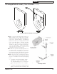
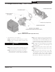
Figure 5: Return Injector Piping and Relief Valve
Assembly Details
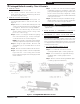
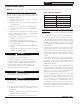
Figure 4D: Burner Swing Door Insulation
Step a. Locate the return pipe fittings and injector.
Apply sealant to the 2” NPT injector threads.
Insert injector into 2” NPT upper rear tapping on
rear section. Thread 2” NPT x 1-1/2” Reducing
Elbow onto 2” NPT injector. Apply thread sealant
to the 1-1/2” NPT nipple. Thread 1-1/2” NPT
nipple into 1-1/2” NPT end of reducing elbow.
Thread 1-1/2” NPT x 1-1/2” NPT x 3/4” NPT Tee
onto 1-1/2” NPT nipple. Tighten pipe fittings
until relief valve orientation is correct for your
installation and joints are watertight.
Note: Based on system return piping and access
to service boiler, see Figures 1, 10 and 11,
predetermine if injector piping orientation is to be
positioned for vertical, horizontal left or horizontal
right side return piping as shown in Figure 5.
Step b. Install relief valve using 3/4" NPT tapping
on tee. Relief valve must be installed in vertical
position. If orientation of return injector piping
is for:
• 1-1/2" NPT vertical return piping - Install
3/4" NPT x 90° street ell (not furnished)
into 3/4” NPT tapping on tee. Install relief
valve vertically into street ell. See Figure
5.
• 1-1/2" NPT horizontal left or right side return
piping - Install relief valve vertically in 3/4"
2 Packaged Boiler Assembly - Trim & Controls (continued)