
Product Overview

42
103859-12 - 8/19
MPO-IQ
Installation & Service Manual
4. Allow burner to run until oil flows from vent
fitting is a SOLID stream without air bubbles for
approximately 10 seconds.
NOTE: For Primary Control "Pump Priming Cycle"
details, see Paragraph J, No. 1., Step b.
5. Close vent fitting and burner flame should start
immediately after pre-purge is completed. Pre-
purge prevents burner flame until 15 seconds has
elapsed after initial power is applied to burner.
During pre-purge the motor and igniter will operate
but the oil valve will remain closed. Refer to Oil
Primary Control Instructions for more details.
6. Adjust oil pressure.
a. When checking a fuel unit's operating pressure,
a reliable pressure gauge may be installed in
either the bleeder port or the nozzle port. Refer
to Burner Manufacturer's Manual for more details.
b. Locate oil pressure adjusting screw and turn
screw to obtain proper pump pressure, refer to
Tables 15A thru 15C and 16 at rear of manual.
c. To check the cut-off pressure, deadhead a reliable
pressure gauge onto the copper connector tube
attached to the nozzle port. Run the burner for
a short period of time. Shut the burner off. The
pressure should drop and hold.
d. Remove the gauge and install bleeder port and/
or reconnect the nozzle port line.
E. ADJUST OIL BURNER WHILE OPERATING. (flame
present)
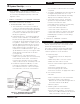
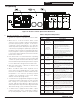
1. ADJUST DRAFT REGULATOR for a draft of zero
inches (water gauge) in the canopy (see Figure 17)
after chimney has reached operating temperature
and while burner is running. (At least five minutes)
See Tables 15A thru 15C and 16 at rear of manual
for details.
2. READJUST THE AIR SETTING on burner for a
light orange colored flame while the draft in the
canopy is zero inches water column ("w.c.). Use
a smoke tester and adjust air for minimum smoke
(not to exceed #1) with a minimum of excess air.
Make final check using suitable instrumentation
to obtain a CO
2
of 11.5 to 13.0% with draft of
zero inches water column ("w.c.) (water gauge)
in canopy. These settings will assure a safe and
efficient operating condition. If the flame appears
stringy instead of a solid fire, try another nozzle of
the same type. Flame should be solid and compact.
After all adjustments are made recheck for a draft
of zero inches water column ("w.c.) in the canopy.
Replace plug at completion.
See Tables 15A thru 15C and 16 (at rear of this
manual) for details regarding the overfire pressure
when baffles are both installed and removed.
3. READJUST THE HEAD SETTING.
It might be necessary to move the head forward or
back one position at a time to optimize the smoke
and CO
2
readings. Refer to Burner Manufacturer's
Manual for details.
4. TURN “OFF” BURNER and remove pressure
gauge. Install gauge port/bleeder plug and
tighten. Start burner again.
WARNING
Do not loosen or remove any oil line fittings while
burner is operating.
5. FLAME FAILURE
The Boiler Control operates the burner automatically.
If for unknown reasons the burner ceases to fire and
the reset button on the primary control has tripped,
the burner has experienced ignition failure. Refer to
Oil Primary Control Features, Paragraph J, Step 2
of this Section and Section XIII, Trouble Shooting,
Paragraph B.
F. CHECK FOR CLEAN CUT OFF OF BURNER.
1. AIR IN THE OIL LINE between fuel unit and
nozzle will compress when burner is on and will
expand when burner stops, causing oil to squirt
from nozzle at low pressure as the burner slows
down and causing nozzle to drip after burner stops.
Usually, cycling the burner operation about 5 to 10
times will eliminate air from the oil line.
2. IF NOZZLE CONTINUES TO DRIP, repeat
Paragraph F, No. 1. If this does not stop the dripping,
remove cut-off valve and seat, and wipe both with a
clean cloth until clean, then replace and readjust oil
pressure. If dripping or after burn persist replace
fuel pump.
G. ADJUST CONTROL SETTINGS
Program boiler control (high limit, etc.) to suit
individual requirements for the installation. Refer
to Section IX "OPERATING" to locate and adjust the
control.
H. SEQUENCE OF OPERATION
The Boiler Control display provides a status display,
"STA", shown in Table 9. Refer to Section IX
"OPERATING" to locate and view the sequence.
I. CHECK THERMOSTAT OPERATION.
Raise and lower thermostat setting as required to
start and stop burner.
8 System Start-Up (continued)
!