
Product Overview


56
103859-12 - 8/19
MPO-IQ
Installation & Service Manual
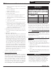
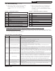
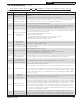
Possible Err (boiler control error) Values:
Err
Value
Description
1
Temperature Sensor Fault
2
Communications Fault
3
Internal Hardware Fault
4
Burner Output (B1) Fault
5
Line Voltage Fault (< 80 Vac)
6
Fuse Missing
7
User Setting Lost, (reset to factory defaults)
8
Manual Reset Lockout (resettable)
Possible STA (status) Values:
sTa
Value
Description
1
Standby
4
Pre-purge
6
Trial for Ignition
7
Carryover
8
Running
9
Post-Purge
10
Retry/Recycle Display
14
Hard Lockout
15
Waiting for Limit to Close
16
Flame Present Out of Sequence
17
Self Test
StA
Status (see Status Numbers)
bt
Boiler Temperature
SP
Operating Setpoint (Outdoor Reset)
HL
High Limit Setpoint
HdF
High Limit Differential
hr
Heat Request Status
dh
DHW Heat Request Status
CAD
Cad Cell Resistance (ohms)
run
Run Time Hours
CYC
Boiler Cycles
Err
Error (see Error Numbers)
Erp
External Device Error (see Error Numbers)
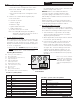
Operating Mode Parameters
Press “I” key on the control to
change from one parameter
to the next. Each setting will
alternate between display
code (for example STA) and
value.
Figure 36: Boiler Control
User Interface
c. Defective nozzle causing flame to be erratic.
d. Excessive airflow or draft causing flame to
leave burner head.
e. Excessive back pressure causing flame to be
erratic.
3. Control locks out after Trial For Ignition (TFI).
a. No oil to burner.
b. Shorted electrodes.
c. Nozzle clogged.
d. Airflow too high.
e. Ignitor module defective.
f. CAD cell defective.
g. Oil valve stuck open or closed.
Note: The Safety Monitoring Circuit (SMC) is
designed to provide lockout in the event of
a stuck or welded motor relay.
C. IQ OIL BOILER CONTROL
When a problem occurs with the boiler operation, the
IQ Control System easily provides specific, valuable
information to help resolve the issue quickly. The
display on the Boiler Control should be the first place
to check, see Figure 36.
1. Error Code "Err" IS NOT displayed on the Boiler
Control: This is one of two conditions that occur
when a problem arises. In this circumstance,
the following table can be used to determine the
problem and possible causes.
NOTICE If flame is not established within 15
seconds of oil valve actuation (known as Trial
For Ignition [TFI]) lockout will occur. Lockout is
indicated by a red LED solid-on located on the oil
primary control.
Hard Lockout will occur if the Oil Primary Control
locks-out three (3) times during a call for heat. This
is indicated by red light reset button solid-on.
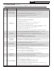
D. BEFORE TROUBLESHOOTING
The following pages contain trouble shooting tables
for use in diagnosing control problems. When using
these tables the following should be kept in mind:
1. This information is only meant to be used by
a professional heating technician as an aid in
diagnosing boiler problems.
2. Where applicable, follow all precautions outlined
in Section IX, System Start-Up .
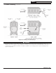
3. In general, these tables assume that there are
no loose or miswired electrical connections.
Before using these tables inspect all electrical
connections on the boiler to make sure that they
are tight. Also, check the wiring on the boiler
against the wiring diagram in Figures 26, 27
and 28. Ensure that incoming 120 Vac power
polarity is correct and that the boiler is properly
grounded.
NOTICE If flame is not established within 15
seconds of oil valve actuation (known as Trial
For Ignition [TFI]) lockout will occur. Lockout is
indicated by a red LED solid-on located on the oil
primary control.
Hard Lockout will occur if the Oil Primary Control
locks-out three (3) times during a call for heat. This
is indicated by red light reset button solid-on.
12 Troubleshooting (continued)