
User Guide


83
Boiler
Model
Burner
Input
(GPH)
Burner
Model
Nozzle
Air
Shutter
(setting)
Air Band
(setting)
Pump
Pressure
(PSI)
Head
Type
(setting)
Insertion
Depth
(Inch)
Approx.
Shipped
CO
2
(%)
Bafe
Location
(pass)
Approx.
Stack Temp.
Increase
Without
Bafes °F
(2)
Approx.
Breech
Pressure
(" w.c.)
(3)
Bafes
IN
Approx.
Overre
Pressure
(" w.c.)
(3)
Bafes
OUT
Approx.
Overre
Pressure
(" w.c.)
(3)
MPO-IQ84 0.60 AFG
0.50 x 45W
Delavan
8
(1)
0 180 L2 2 11.5 3
rd
52 0 +0.010 +0.005
MPO-IQ115 0.80 AFG
0.60 x 45W
Delavan
5 0 180 L2 2 11.5 2
nd
& 3
rd
84 0 +0.040 +0.020
MPO-IQ147 1.05 AFG
0.75 x 60B
Delavan
9 0 180 L1 2 11.5 2
nd
65 0 +0.040 +0.020
MPO-IQ189 1.35 AFG
1.00 X 60B
Delavan
7 1 180 V1 (2) 2 11.5 2
nd
39 0 +0.040 +0.030
MPO-IQ231 1.65 AFG
1.25 x 60B
Hago
10 3 180 V1 (3) 2 11.5 2
nd
18 0 +0.050 +0.030
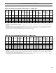
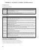
Notes
(1)
MPO-IQ84 at 0.60 GPH ring rate utilizes a low re bafe.
(2)
The increased stack temperature with the bafes removed is an approximation, based on a constant supply temperature of 180°F and 11.5% CO
2
. Actual eld conditions may
be different.
(3)
These values are minimum and could be as much as -.03" w.c., more without impacting performance. Pressures based on 11.5% CO
2
. Example: MPO-IQ231 could have a
breech pressure of -.03" w.c. and an overre pressure of .020" w.c.
(4) Single stage fuel pump is standard, two-stage fuel pump is optional. Burner manufacturer has preset single stage fuel pump to settings shown in table above. Two-stage
fuel pump is factory set at 140 PSI and must be readjusted to settings shown above during burner start-up.
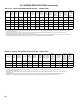
TABLE 15A: BECKETT AFG BURNER SPECIFICATIONS - CHIMNEY VENT
Boiler
Model
Burner
Input
(GPH)
Burner
Model
Nozzle
Air Gate
(setting)
Turbulator
(setting)
Pump
Pressure
(PSI)
Combustion
Head
Insertion
Depth
(Inch)
Approx.
Shipped
CO
2
(%)
Bafe
Location
(pass)
Approx.
Stack Temp.
Increase
Without
Bafes °F
(2)
Approx.
Breech
Pressure
(" w.c.)
(3)
Bafes
IN
Approx.
Overre
Pressure
(" w.c.)
(3)
Bafes
OUT
Approx.
Overre
Pressure
(" w.c.)
(3)
MPO-IQ84 0.60 F3
.50 x 80°W
Delavan
2.5 1.0 145 SBT 6" 2.25 11.5 3
rd
52 0 +0.010 +0.005
MPO-IQ115 0.80 F3
.65 x 70°W
Delavan
5.0 3.0 145 VSBT 2.25 11.5 2
nd
& 3
rd
84 0 +0.040 +0.020
MPO-IQ147 1.05 F5
0.85 x 60°B
Delavan
2.7 1.0 145 LBT 10.0" 10 11.5 2
nd
65 0 +0.040 +0.020
MPO-IQ189 1.35 F5
1.10 x 60°B
Delavan
4.5 3.0 150 SBT 6" 3.5 11.5 2
nd
39 0 +0.040 +0.030
MPO-IQ231 1.65 F5
1.35 x 60°B
Delavan
3.5 4.0 145 VSBT 2.25 11.5 2
nd
18 0 +0.050 +0.030
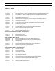
Notes
(2)
The increased stack temperature with the bafes removed is an approximation, based on a constant supply temperature of 180°F and 11.5% CO
2
. Actual eld conditions may
be different.
(3)
These values are minimum and could be as much as -.03" w.c., more without impacting performance. Pressures based on 11.5% CO
2
. Example: MPO-IQ231 could have a
breech pressure of -.03" w.c. and an overre pressure of .020" w.c.
(4) Single stage fuel pump is standard, two-stage fuel pump is optional. Burner manufacturer has preset single stage fuel pump to settings shown in table above. Two-stage fuel
pump is factory set at 140 PSI and must be readjusted to settings shown above during burner start-up.
TABLE 15B: RIELLO 40 BURNER SPECIFICATIONS - CHIMNEY VENT
XV. BURNER SPECIFICATIONS