
Install Instructions

45
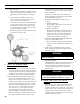
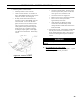
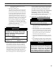
Figure 26: Cad Cell Location
SECTION VIII: SYSTEM START-UP (continued)
c. Simulate Ignition or Flame Failure:
• Follow procedure to turn on burner.
• Check cad cell resistance. If resistance is
below 1600 OHMS and burner runs beyond
safety cut-out time, cad cell is good.
• If safety switch shuts down burner and
resistance is above 1600 OHMS, open line
switch to boiler. Access cad cell under
ignitor, clean face of cad cell and see that
cell is securely in socket, see Figure 26.
Check gasket around perimeter of ignitor
lid for proper seal. If gasket is missing
or damaged, replace gasket. Room light
can effect cad cell resistance. Reset safety
switch.
• Close line switch to boiler. If burner starts
and runs beyond safety switch cut-off time,
cell is good. If not, install new cell.
• Close hand valve in oil supply line.
• Failure occurs, device enters Recycle Mode.
• Device tries to restart system after
approximately 60 seconds.
• After third Recycle Mode trial, safety
switch locks out within safety switch
timing indicated on label and control enters
Restricted Mode.
d. Power Failure Check: After Flame is established,
turn the power off to the control/burner. The
burner should shut down safely. When power is
restored a normal ignition sequence should be
started.
WARNING
Cad Cell Jumper must be removed after this
check.
K. IF CONTROLS DO NOT MEET
REQUIREMENTS outlined in Paragraph I., replace
control and repeat checkout procedures.