
Install Instructions


67
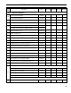
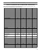
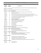
APPENDIX A - FIGURES
Figure
Number
Page
Number
Description
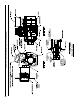
Figure 1 5 MST288 Thru MST629 Steam Boiler with and without Tankless Heater (Beckett Burner Shown)
Section I - Pre-Installation
Figure 2 7 Minimum Installation Clearances to Combustible Materials (Inches)
Section II - Unit-Pak Boiler Assembly
Figure 3 9 MegaSteam Unit-Pak Boiler Shipment Contents (outside container removed)
Figure 4 11 Boiler Removal from Skid
Figure 5A 12 Partial Front View - Burner Swing Door Mounted to Boiler - Fully Closed and Secured
Figure 5B 13 Top View - Burner Swing Door Mounted to Cast Iron Block Assembly (Jacket Removed for Clarity)
Figure 5C 14 Top View - Burner Swing Door Fully Closed but Not Properly Secured or Sealed
Figure 6 15 Flueway Bafe Positioning/Orientation in Flueways
Figure 7 16 Purpose of Tappings and Bosses
Figure 8 18 Pressure Limit Installation
Figure 9 19 Float-Type LWCO and Pressure Limit Installation
Figure 10 21 Oil Burner Installation (Beckett Burner Shown)
Figure 11A 22 Installation/Removal of Drawer Assembly
Figure 11B 22 Nozzle Replacement
Figure 11C 22 Electrode Setting
Figure 11D 23 Turbulator Setting
Figure 11E 23 Pump Connections and Port Identication
Section III - Steam Boiler Piping & Trim
Figure 12 25 Recommended Boiler Piping for Gravity Return Steam Boiler
Section IV - Tankless & Indirect Water Heater Piping
Figure 13 27 Schematic Tankless Water Heater Piping
Figure 14 28 Alliance SL Water Heater Piping with MegaSteam Boiler
Section V - Venting & Air Intake Piping
Figure 15 30 Recommended Vent Pipe Arrangement and Chimney Requirements
Figure 16 30 Proper and Improper Locations of Draft Regulator
Figure 17 31 Smokebox Pressure Tapping for Checking Draft at Breech
Section VI - Electrical
Figure 18 34 Wiring Diagram, Hydrolevel CG450 Probe LWCO
Figure 18A 35 Wiring Diagram, McDonnell & Miller PS-801 Probe LWCO
Figure 18B 36 Wiring Diagram, McDonnell & Miller #67 Float LWCO
Figure 19 37 Wiring Diagram, Wiring Diagram, All Burner Options with Various Oil Primary Controls
Section VII - Oil Piping
Figure 21 39 Single Pipe Oil Line
Figure 22 40 Two Pipe Oil Lines